Side rail and combined oil control ring incorporated with the side rails for reduction of oil consumption

a combined oil control and side rail technology, applied in the direction of brake systems, machines/engines, transportation and packaging, etc., can solve the problems of increasing lubricant consumption, not producing any practical effect to improve followability, and the outer surface of the side rail cannot always produce oil film of suitable thickness on the inner surface of the cylinder, so as to improve wear resistance and scrape efficiently

Inactive Publication Date: 2006-05-02
RIKEN CO LTD
View PDF7 Cites 22 Cited by
  • Summary
  • Abstract
  • Description
  • Claims
  • Application Information

AI Technical Summary

Benefits of technology

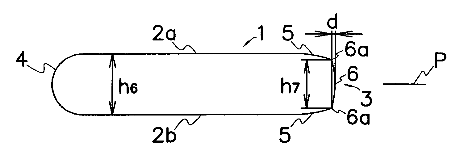
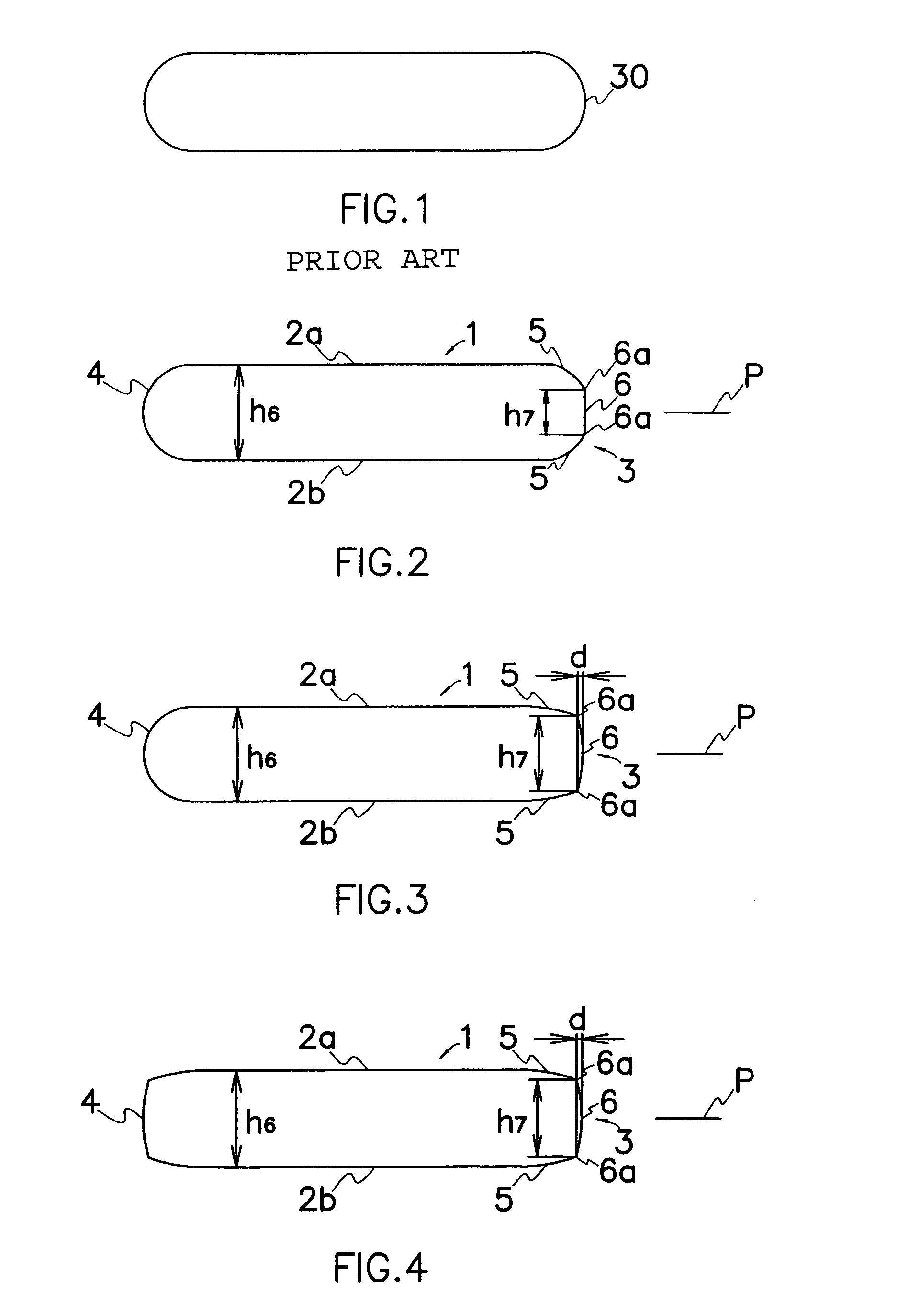
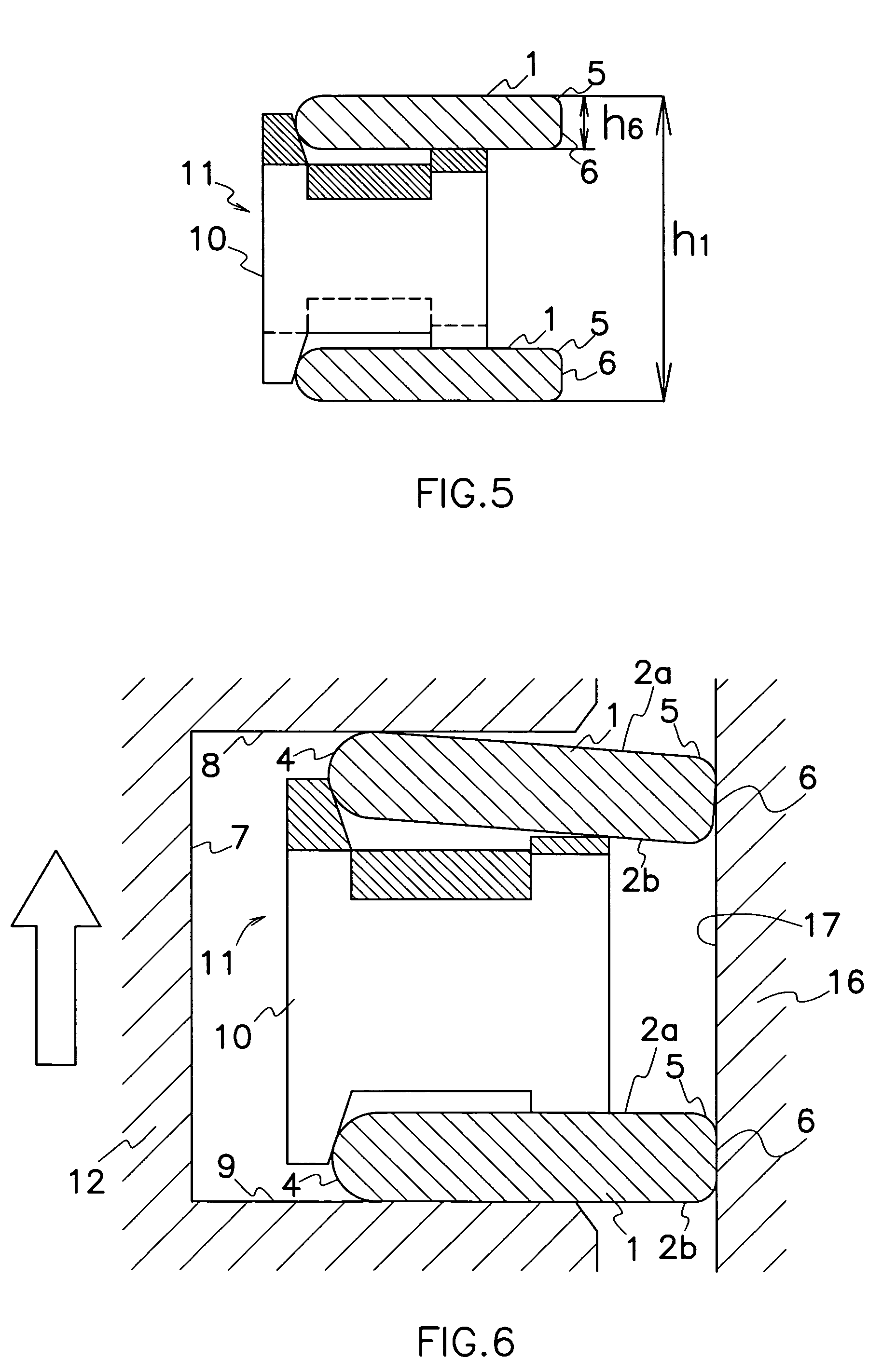
[0010]A side rail (1) according to the present invention is formed into a ring shape having its generally rectangular section that comprises a pair of side surfaces (2a, 2b) in parallel to each other, an outer surface (3) formed between two outer peripheries of the side surfaces (2a, 2b) for contact to an inner surface (17) of a cylinder (16), and an inner surface (4) formed between two inner peripheries of the side surfaces (2a, 2b) for contact to a spacer expander (10) of the oil control ring. The outer surface (3) comprises a pair of edge surfaces (5) connected to the adjacent side surfaces (2a, 2b), and an intermediate surface (6) formed between the edge surfaces (5). The edge surface (5) is formed with a smaller radius than that of a prior art barrel-shaped surface (30) so that the edge surface (5) can easily ride on oil film on cylinder (16) in the inclined condition of the side rail (1) in operation and allow the side rail (1) to perform smooth sliding movement on the inner surface (17) of cylinder (16). The intermediate surface (6) is formed with a greater radius of curvature than that of the prior art barrel-shaped surface (30) to efficiently scrape lubricating oil on cylinder (16) when the side rail (1) is in the non-inclined condition, thereby forming lubricating oil film of necessary and minimum thickness between the inner surface (17) of cylinder (16) and side rail (1). Also, the larger radius of curvature for forming the intermediate surface (6) provides a larger contact area to the inner surface (17) of cylinder (16) to improve wear resistance.

Problems solved by technology

Accordingly, smaller tension of the spacer expander would be desirable for nimble reciprocal movement of the piston but on the other hand such a spacer expander may result in increase of lubricant consumption because it deteriorates followability in operation of the side rail to cylinder, and therefore, the outer surface of the side rail does not keep close sliding contact to the deformed inner surface of cylinder.
The combined oil control ring comprises a spacer expander and two side rails attached to the spacer expander in axially spaced relation to each other wherein axial distance between outer tips of the upper and lower side rails is shorter than axial distance between imaginary central planes passing through the upper and lower side rails to improve mating distortion or followability of the side rails to deformed inner surface of cylinder in operation, but it does not produce any practical effect to better the followability.
Although the side rail comes into contact to the inner surface of cylinder under elastic force of spacer expander, it is believed that the round outer surface of the side rail can neither always produce oil film of suitable thickness on inner surface of cylinder in the inclined and non-inclined conditions of the side rail nor scrape up and down sufficient amount of lubricating oil from inner surface of cylinder.
In particular, when the oil control ring is incorporated with side rails of lower tension for reducing pressing force of side rails on inner surface of cylinder, it has been found that the oil control ring would increase oil consumption.

Method used


Image

  • Side rail and combined oil control ring incorporated with the side rails for reduction of oil consumption
  • Side rail and combined oil control ring incorporated with the side rails for reduction of oil consumption
  • Side rail and combined oil control ring incorporated with the side rails for reduction of oil consumption

Examples


Embodiment Construction

[0019]Embodiments of the present invention will be described hereinafter in connection with the accompanied drawings.

[0020]As shown in FIG. 1, a prior art side rail has been contoured with barrel-shaped outer and inner surfaces 30 even though they have been provided with surface modification for improvement of sliding performance. Conveniently, the barrel-shaped surfaces 30 can coincidentally be formed upon rolling of steel wires into flat section to cause the outer and inner surfaces 30 to radially expand into a barrel shape of substantially constant radius of curvature.

[0021]As shown in FIG. 2, the side rail according to the present invention is formed into a ring shape having its generally rectangular section that comprises a pair of radial side surfaces 2a, 2b in parallel to each other, an outer circumferential surface 3 formed between two outer peripheries of the side surfaces 2a, 2b, and an inner circumferential surface 4 formed between two inner peripheries of side surfaces 2...


PUM


Abstract

A side rail is formed into a ring shape having its generally rectangular section that has an outer surface 3 formed with a pair of edge surfaces 5 of small radius, and an intermediate surface 6 of large radius of curvature formed between the edge surfaces 5. When the side rail is in the inclined condition in operation, each edge surface 5 can easily ride on oil film on cylinder 16 and allow the side rail 1 to perform smooth sliding movement on the inner surface of cylinder. The intermediate surface 6 efficiently scrapes lubricating oil on cylinder to form lubricating oil film of necessary and minimum thickness between an inner surface 17 of cylinder 16 and side rail 1. Also, the larger radius of curvature for forming the intermediate surface 6 provides a larger contact area to the inner surface 17 of cylinder 16 to improve wear resistance.

Description

[0001]This invention relates to a side rail for oil control ring used in an internal combustion engine, in particular a side rail and a combined oil control ring incorporated with the side rails demonstrating an excellent control function of lubricating oil on cylinder.BACKGROUND OF THE INVENTION[0002]An oil control ring is attached in a ring groove formed on a cylindrical outer surface of a piston to control lubricating oil on an inner surface of a cylinder in an internal combustion engine. A typical example of currently practical oil control rings is a combined oil control ring that comprises a spacer expander and a single or a pair of side rails attached to the spacer expander. In operation of the internal combustion engine, the side rail is retained in a ring groove of the piston, while the side rail is reciprocated in a cylinder along with the piston to cause an outer surface of the side rails to slide on the inner surface of the cylinder. At the same time, the spacer expander ...

Claims


Application Information

Patent Timeline
Patent Type & Authority Patents(United States)
IPC IPC(8): F02F5/00F16J9/06F16J9/20
CPCF16J9/068F16J9/064F16J9/06
Inventor TAKIGUCHI, KATSUMIKUSAMA, KAZUNORI
Owner RIKEN CO LTD
Why Eureka
Try Eureka