Electromagnet for use in a relay

a technology of electromagnet and relay, which is applied in the direction of transformer/inductance magnetic core, magnet, magnetic body, etc., can solve the problems of iron core and coil bobbin displacement, deficiency has not been surely prevented, and the disengagement of iron core and coil bobbin, etc., to prevent misregistration, facilitate process operation, and simple structure

Active Publication Date: 2011-02-10
PANASONIC CORP
View PDF13 Cites 1 Cited by
  • Summary
  • Abstract
  • Description
  • Claims
  • Application Information

AI Technical Summary

Benefits of technology

[0016]According to the electromagnet for use in a relay of the present invention, the other end (open end) of the body portion of the iron core projected out of the opening of the flange portion of the coil bobbin when the coil bobbin is externally fitted onto the iron core is provided with a portion to be engaged corresponding to the engaging portion formed on the grasping part side of the coil winding chuck device, so that when the other end of the iron core is grasped with the chuck device and coil is wound, the engagement structure supplements grasping of the chuck device and the iron core is prevented from being slipped out of the chuck device.
[0017]Further according to the electromagnet for use in a relay of the present invention in which the misregistration prevention means is further provided, misregistration of the coil bobbin and the iron core which may be caused during coil winding operation can be prevented.
[0018]Specifically, according to the electromagnet for use in a relay of the present invention in which the projected piece formed on the coil bobbin side is pressed against the body portion of the iron core to fix the coil bobbin and the iron core, misregistration can be prevented with a simple structure. In addition, the iron core is not required to be processed, so that the process operation is facilitated.
[0019]According to the present invention in which the iron core and the coil bobbin are engaged and fixed with the engaging claw formed on one of the contacting surfaces and the engageable hole formed on the other surface, when they are once engaged, they can be fixed without misregistration.
[0020]According to the present invention in which the slip-out prevention means is further provided, slipping-out of the iron core from the coil bobbin, which is easily occurred, can be prevented.
[0021]According to the present invention in which the projection formed at the outer circumference of the other end of the body of the iron core is designed to be engaged to the flange portion of the coil bobbin, when they are once coupled, its coupling force is strong and there is no fear of slip-out of the iron core from the opening of the coil bobbin.

Problems solved by technology

However, when the grasping degree of the iron core with the coil winding chuck device and the engagement degree of the coil bobbin and the iron core are not enough, there is a high possibility that the iron core is disengaged from the coil winding chuck device, the iron core and the coil bobbin are displaced, and the iron core is slipped out of the coil bobbin.
However, such deficiency has not been surely prevented and specific preventive measures have been required for improving the structure of the object to be wound and the coil winding chuck device.

Method used


Image

  • Electromagnet for use in a relay
  • Electromagnet for use in a relay
  • Electromagnet for use in a relay

Examples


Embodiment Construction

[0033]The embodiment of the present invention is explained referring to the attached drawings.

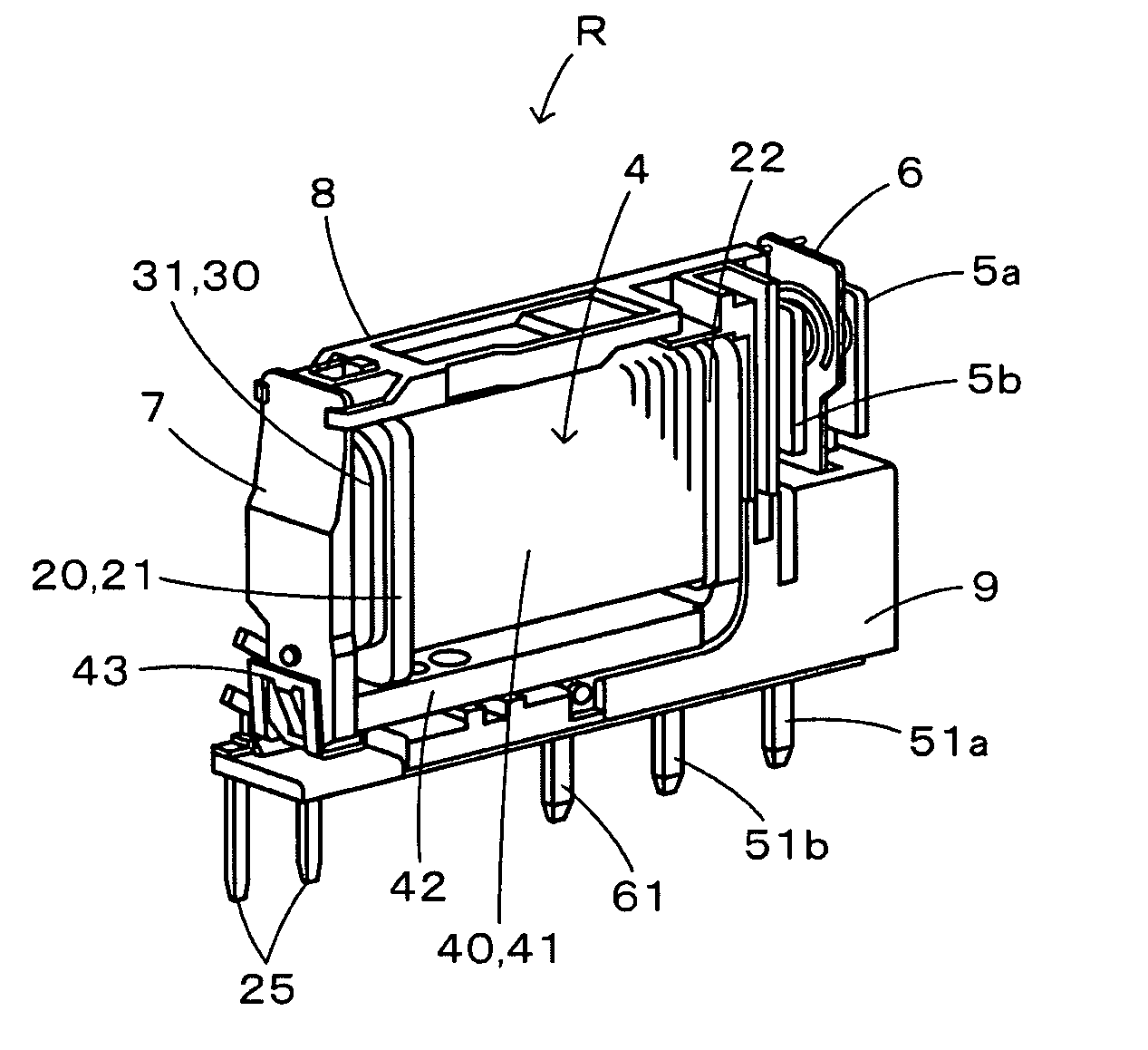
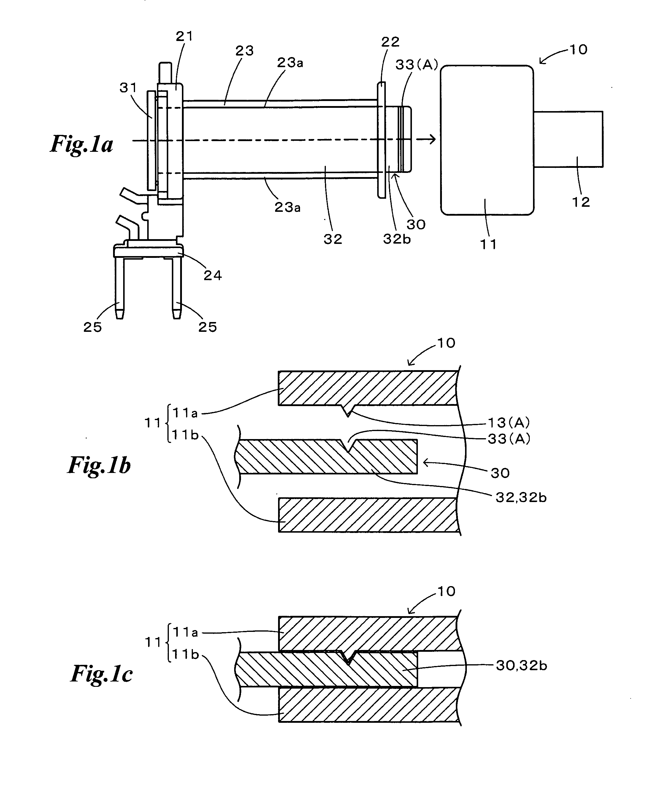
[0034]FIG. 6 and FIG. 7 are explanatory views of each member of electromagnet for use in a relay of several kinds of embodiments of the present invention to be explained later. At first the diagrammatic structure of the electromagnet for use in a relay is explained referring to these figures. The structural characteristics of each embodiment, mentioned later, are not shown in these figures.

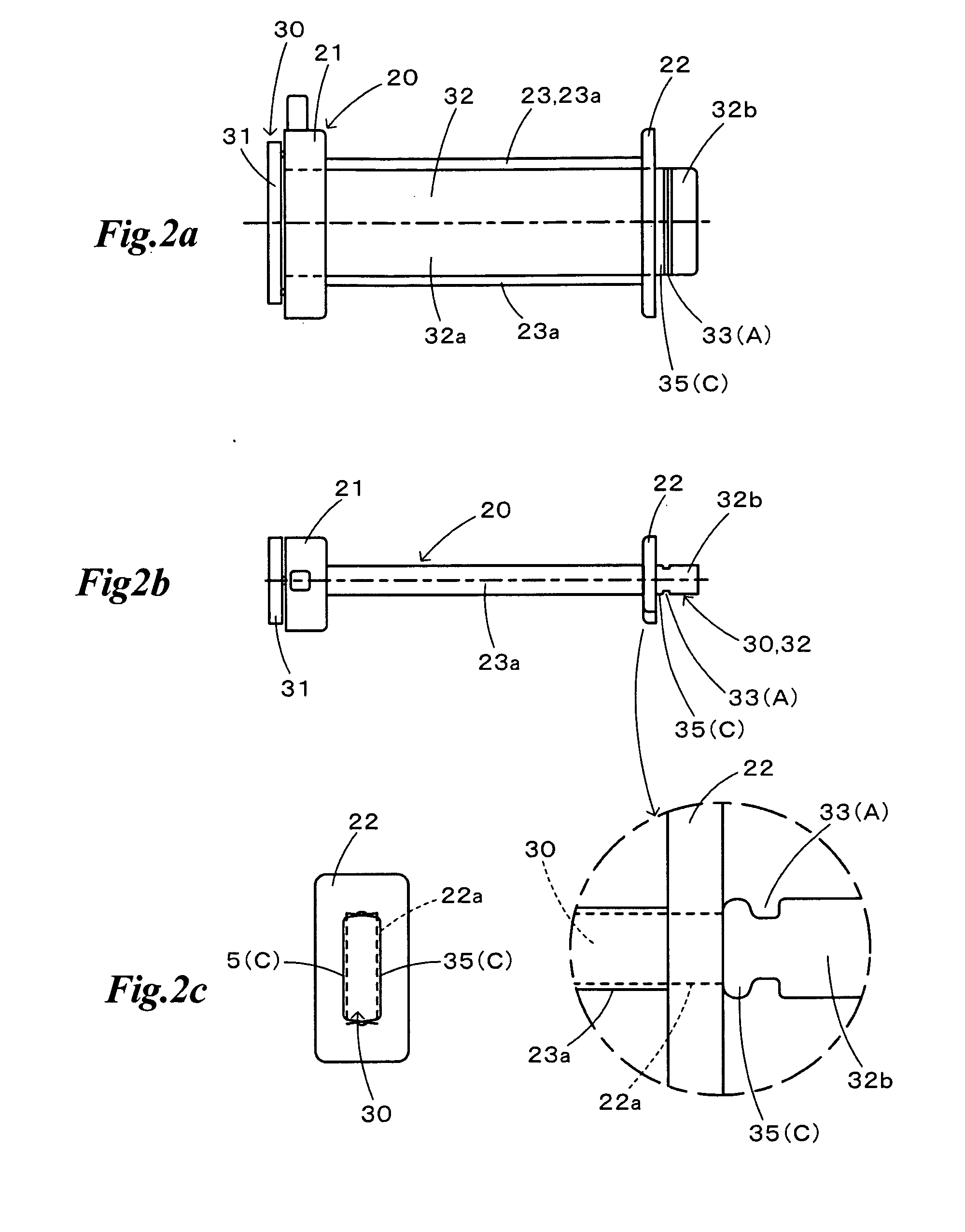
[0035]FIG. 6 is an explanatory view showing the structure of the coil bobbin and the iron core which are structural members of an electromagnet for use in a relay, FIG. 6a is a perspective view of the unengaged condition, and FIG. 6b is a perspective view of the engaged condition.

[0036]A coil bobbin 20 constituting an electromagnet for use in a relay 1 (see FIG. 7) is made of resin and is provided with a coil winding part 23 to be wound with coil 40 (see FIG. 7) and the first and the second flange portion...


PUM

PropertyMeasurementUnit
circumferenceaaaaaaaaaa
poweraaaaaaaaaa
structureaaaaaaaaaa

Abstract

An electromagnet for use in a relay having a coil bobbin with flange portions at both ends of a coil winding portion where a coil is wound and an iron core with a flange-like head portion at one end of a body portion, the coil bobbin being so fitted onto the iron core that the flange-like head portion and the other end of the body portion of the iron core respectively project out of each of openings formed at the flange portions of the coil bobbin. The iron core has at the other end an engageable portion to be engaged with an engaging portion formed on a grasping part of a coil winding chuck device. The electromagnet further has between the coil bobbin and the iron core a means for preventing misregistration of the coil bobbin fitted onto the iron core.

Description

TECHNICAL FIELD[0001]The present invention relates to an electromagnet for use in a relay for use as a structural member of an electromagnetic relay, wherein a coil bobbin is externally fitted onto an iron core to be wound with a coil.BACKGROUND ART[0002]For manufacturing an electromagnet for use in a relay, winding operation of coil on a coil bobbin is executed such that after the coil bobbin is externally fitted onto the iron core, the end of the iron core projected out of a flange opening of the coil bobbin is held with a coil winding chuck device to be fixed considering the operation efficiency.[0003]However, when the grasping degree of the iron core with the coil winding chuck device and the engagement degree of the coil bobbin and the iron core are not enough, there is a high possibility that the iron core is disengaged from the coil winding chuck device, the iron core and the coil bobbin are displaced, and the iron core is slipped out of the coil bobbin.[0004]FIG. 10 is an ex...

Claims


Application Information

Patent Timeline
Patent Type & Authority Applications(United States)
IPC IPC(8): H01F3/00
CPCH01H49/00H01H50/36H01F7/127H01H2050/446H01H50/44
Inventor KATO, YOSHIMASA
Owner PANASONIC CORP
Why Eureka
Try Eureka