Antenna Apparatus with Adaptive Polarization Switching Function

an antenna apparatus and adaptive technology, applied in the direction of antenna details, polarised antenna unit combinations, antennas, etc., can solve the problems of poor transmission efficiency and inability to adjust based on data

Inactive Publication Date: 2011-02-10
RALINK TECHNOLOGY CORP
View PDF3 Cites 64 Cited by
  • Summary
  • Abstract
  • Description
  • Claims
  • Application Information

AI Technical Summary

Benefits of technology

[0009]The present invention discloses an antenna device with an adaptive polarization switching function. The antenna device includes an antenna array and a feeding unit. The antenna array includes a first linear polarization antenna and a second linear polarization antenna. The first linear polarization antenna and the second linear polarization antenna have polarization directions orthogonal to each other. The feeding unit includes an input terminal for receiving a transmission signal, a first output terminal coupled to the first linear polarization antenna, and a second output terminal coupled to the second linear polarization antenna. The feeding unit distributes energy of the transmission signal to the first output terminal and the second output terminal according to a control signal so as to generate feeding signals of the first linear polarization antenna and the second linear polarization antenna and to make the feeding signals have a phase difference.
[0010]The present invention further discloses a wireless device, including an antenna array, a feeding unit and a signal processing unit. The antenna array includes a first linear polarization antenna and a second linear polarization antenna. The first linear polarization antenna and the second linear polarization antenna have polarization directions orthogonal to each other. The feeding unit includes an input terminal for receiving a transmission signal, a first output terminal coupled to the first linear polarization antenna, and a second output terminal coupled to the second linear polarization antenna. The feeding unit distributes energy of the transmission signal to the first output terminal and the second output terminal according to a control signal so as to generate feeding signals of the first linear polarization antenna and the second linear polarization antenna according to a control signal and to make the feeding signals have a phase difference. The signal processing unit is utilized for generating the transmission signal.

Problems solved by technology

In the prior art, each antenna in a MIMO system has a fixed polarization direction, and is unable to be adjusted based on system requirements.
Under such circumstances, the antennas of transmitting terminals and receiving terminals may have polarization loss due to polarization mismatch, which results in poor transmission efficiency.

Method used


Image

  • Antenna Apparatus with Adaptive Polarization Switching Function
  • Antenna Apparatus with Adaptive Polarization Switching Function
  • Antenna Apparatus with Adaptive Polarization Switching Function

Examples


Embodiment Construction

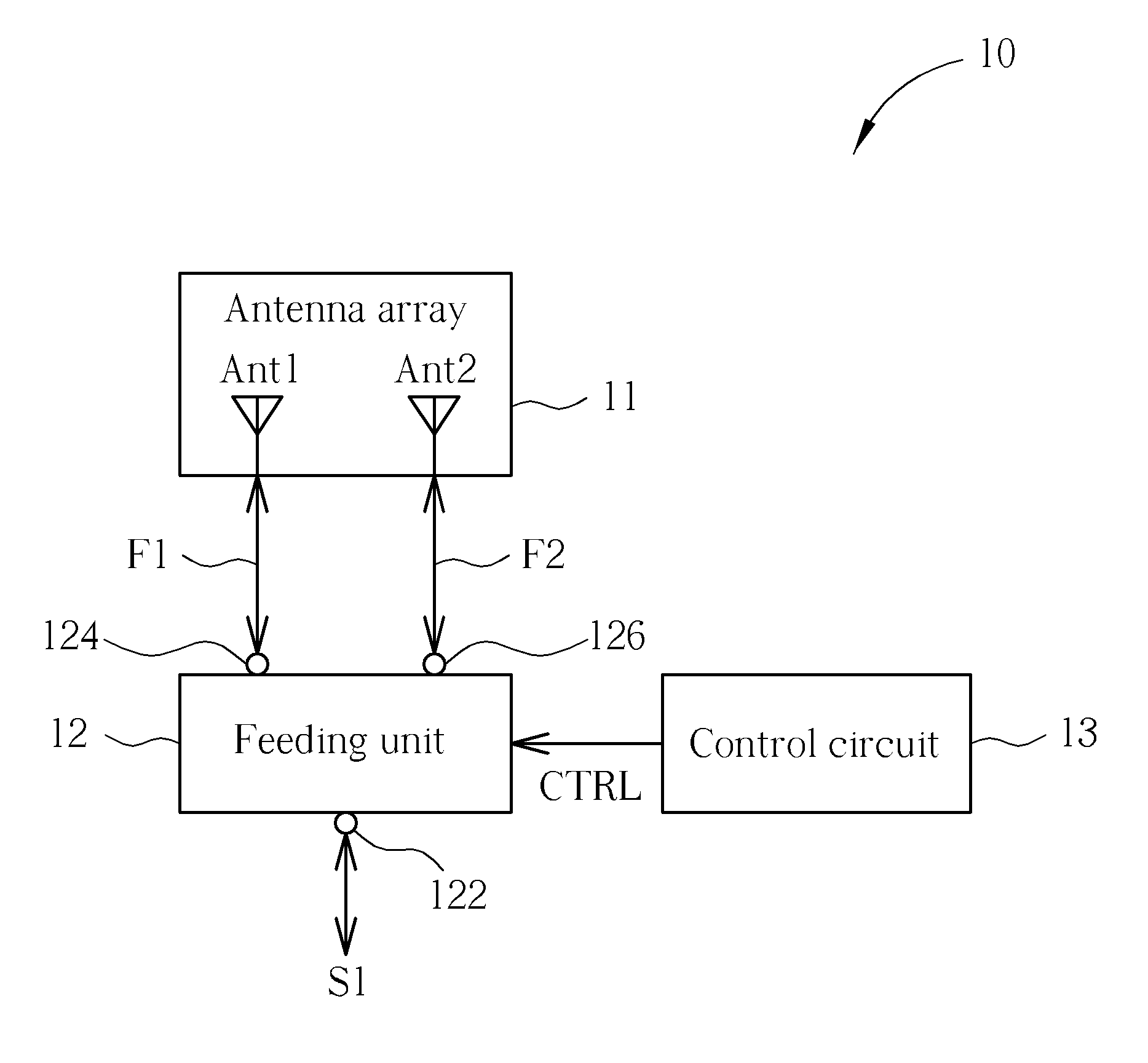
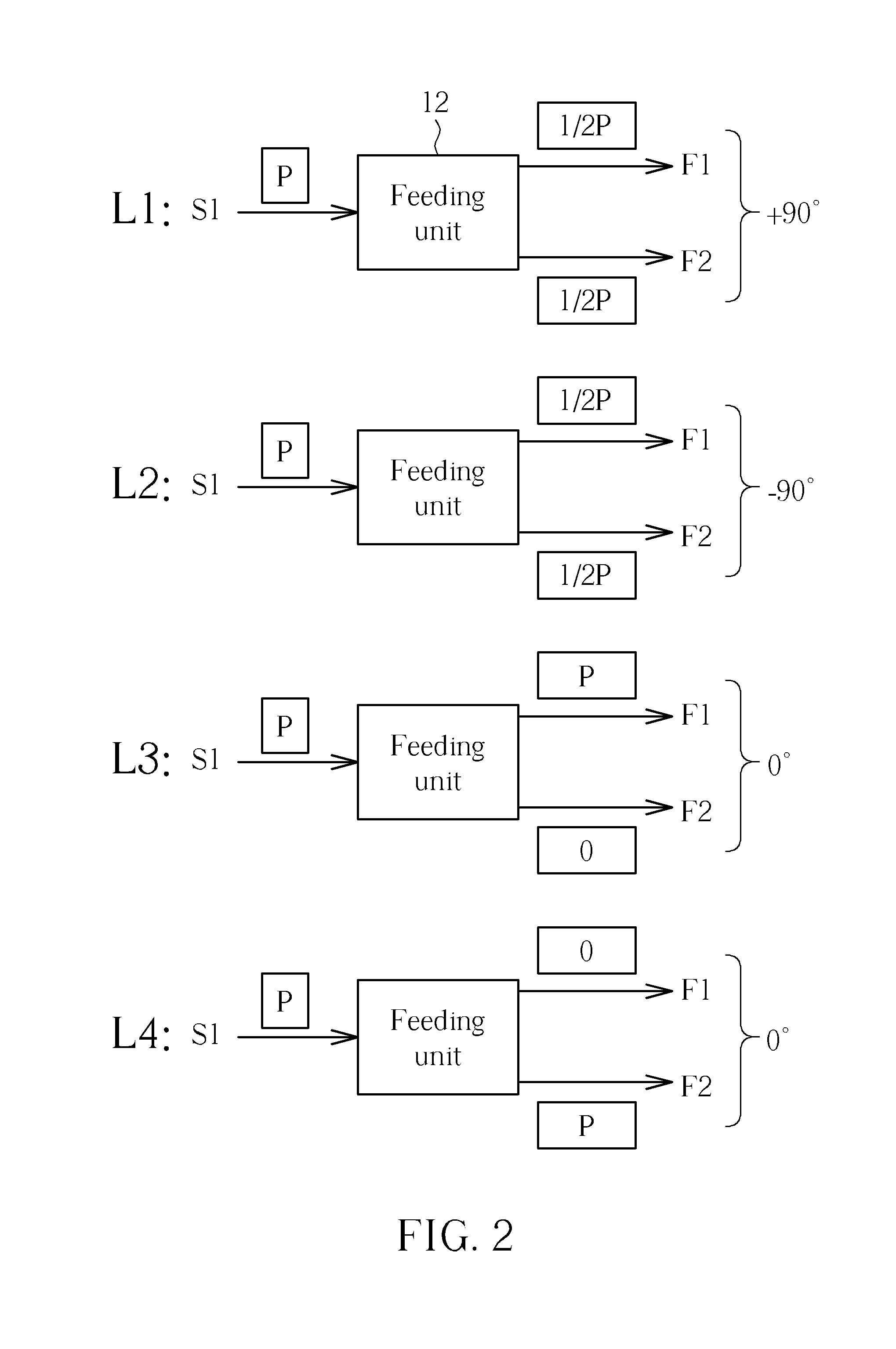
[0017]Please refer to FIG. 1. FIG. 1 shows an antenna device 10 with an adaptive polarization switching function according to an embodiment of the present invention. The antenna device 10 is utilized for performing reception and transmission of radio signals, and includes an antenna array 11 and a feeding unit 12. The antenna array 11 includes linear polarization antennas Ant1 and Ant2 having polarization directions orthogonal to each other. The feeding unit 12 includes an input terminal 122 and output terminals 124 and 126. The input terminal 122 is utilized for receiving a transmission signal S1, and the output terminals 124 and 126 are coupled to the linear polarization antennas Ant1 and Ant2 of the antenna array 11, respectively. The feeding unit 12 distributes energy of the transmission signal S1 to the output terminals 124 and 126 according to a control signal CTRL, so as to generate feeding signals F1 and F2 of the linear polarization antenna Ant1 and Ant2, and to make the fe...


PUM


Abstract

An antenna device with an adaptive polarization switching function, the antenna device including an antenna array comprising a first linear polarization antenna and a second linear polarization antenna, the first linear polarization antenna and the second linear polarization antenna having polarization directions orthogonal to each other, and a feeding unit comprising an input terminal for receiving a transmission signal, a first output terminal coupled to the first linear polarization antenna, and a second output terminal coupled to the second linear polarization antenna, wherein the feeding unit distributes energy of the transmission signal to the first output terminal and the second output terminal according to a control signal so as to generate feeding signals of the first linear polarization antenna and the second linear polarization antenna and to make the feeding signals have a phase difference.

Description

BACKGROUND OF THE INVENTION[0001]1. Field of the Invention[0002]The present invention relates to an antenna device with an adaptive polarization switching function, and more particularly, to an antenna device that switches polarization directions by adjusting energy proportion and phase difference of signals outputted to two linear polarization antennas.[0003]2. Description of the Prior Art[0004]An electronic product with a wireless communication function, such as laptop, PDA (Personal Digital Assistant), etc, radiates and receives radio waves via antennas, to transmit or exchange radio signals, so as to access a wireless network. Hence, for enabling users to access the wireless network in a more convenient way, a bandwidth of an ideal antenna should be as large as possible within limitations, whereas a size thereof should be as small as possible to meet requirements of compact size electronic products.[0005]In addition, with development of wireless communication techniques, quantit...

Claims


Application Information

Patent Timeline
Patent Type & Authority Applications(United States)
IPC IPC(8): H01Q21/24H01Q1/24
CPCH01Q21/08H01Q21/245H01Q21/24
Inventor WU, MIN-CHUNGLO, SHAO-CHIN
Owner RALINK TECHNOLOGY CORP
Why Eureka
Try Eureka