Driving apparatus for light emitting diodes

a technology of light-emitting diodes and driving apparatuses, which is applied in the direction of electrical apparatus, instruments, light sources, etc., can solve the problems of uncompetitive traditional illumination light sources, large volume, and large volume, and achieve the effect of increasing the lifetime of the ac-dc driver for leds and large capacitan

Active Publication Date: 2011-02-17
NANJING UNIV OF AERONAUTICS & ASTRONAUTICS +1
View PDF2 Cites 45 Cited by
  • Summary
  • Abstract
  • Description
  • Claims
  • Application Information

AI Technical Summary

Benefits of technology

[0009]Accordingly, the present invention is directed to a driving apparatus configured to suit driving at least a string of LEDs, wherein a pulsating current is used to drive the high power LEDs so that not only a power

Problems solved by technology

In fact, LEDs have the above-mentioned advantages so that any traditional illumination light sources (for example, incandescent bulb and fluorescent lamp) are uncompetitive with the LEDs.
Although the architecture of the AC-DC

Method used


Image

  • Driving apparatus for light emitting diodes
  • Driving apparatus for light emitting diodes
  • Driving apparatus for light emitting diodes

Examples


Embodiment Construction

[0029]In the following, the depicted embodiments together with the included drawings are intended to explain the feasibility of the present invention.

[0030]Reference will now be made in detail to the present preferred embodiments of the invention, examples of which are illustrated in the accompanying drawings. Wherever possible, the same reference numbers are used in the drawings and the description to refer to the same or like parts.

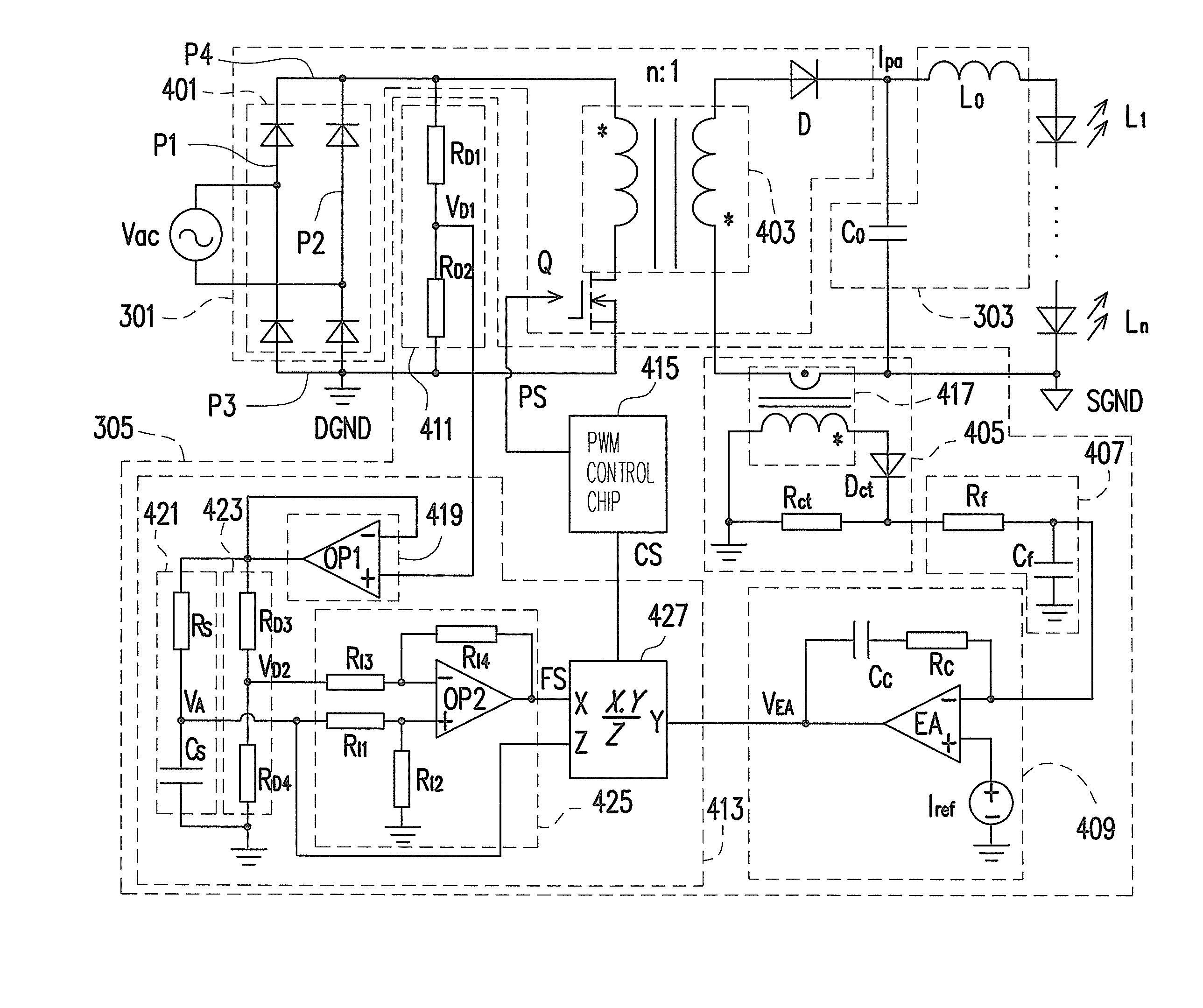
[0031]FIG. 3 is a block chart of a driving apparatus 300 according to an embodiment of the present invention and FIG. 4 is an implemented circuit diagram of the driving apparatus 300 according to an embodiment of the present invention. Referring to FIGS. 3 and 4, a driving apparatus 300 is suitable for driving at least a string of light emitting diodes (LEDs) with large power L1-Ln, wherein the plurality of LEDs are connected to each other in series. The driving apparatus 300 includes a power factor correction (PFC) flyback converter 301, a harmonics-fi...


PUM


Abstract

A driving apparatus is provided and configured to suit driving at least a string of light emitting diodes (LEDs). The driving apparatus includes a flyback power factor correction (PFC) converter, a harmonics-filtering unit and a control unit. The flyback PFC converter works in an operation mode according to a pulse-width modulation (PWM) signal and receives an AC power so as to convert the AC power into a pulsating current. The harmonics-filtering unit is coupled to the flyback PFC converter and the string of LEDs, for receiving the pulsating current and filtering out the high-frequency harmonic components in the pulsating current so as to drive the string of LEDs. The control unit is coupled to the flyback PFC converter and the harmonics-filtering unit, for producing the PWM signal according to the AC power and the pulsating current, and reducing the peak-to-average ratio (PAR) of the pulsating current.

Description

CROSS-REFERENCE TO RELATED APPLICATION[0001]This application claims the priority benefit of U.S.A. provisional application Ser. No. 61 / 233,833, filed on Aug. 14, 2009. The entirety of the above-mentioned patent application is hereby incorporated by reference herein and made a part of specification.BACKGROUND OF THE INVENTION[0002]1. Field of the Invention[0003]The present invention generally relates to a driving apparatus for light emitting diodes (LEDs), and more particularly, to a driving apparatus for LEDs without employing an electrolytic capacitor.[0004]2. Description of Related Art[0005]Since the last 20 years, people have been keeping developing new types of illumination light sources. The European Union specifically worked out “Rainbow Project”, wherein it is addressed that a new type light source must meet the following four conditions: high-efficiency, energy-saving, pollution-free and resembling natural light. In fact, LEDs have the above-mentioned advantages so that any ...

Claims


Application Information

Patent Timeline
IPC IPC(8): H05B41/36
CPCH05B45/385
Inventor WANG, BEIBEIRUAN, XINBOXU, MINGYAO, KAI
Owner NANJING UNIV OF AERONAUTICS & ASTRONAUTICS
Why Eureka
Try Eureka