Power control circuit for wire compensation and compensation method of the same

Inactive Publication Date: 2011-02-17
NIKO SEMICON
View PDF1 Cites 9 Cited by
  • Summary
  • Abstract
  • Description
  • Claims
  • Application Information

AI Technical Summary

Benefits of technology

[0008]Accordingly, it is a main object of the present invention to provide a power control circuit with the function of wire compensation, which is able to compensate the voltage drop on the power wire without the need of using the detecting wire as mentioned above to sense the actual voltage received by the load.
[0010]As a preferred embodiment, the adaptive sensing circuit comprises a feedback circuit and a compensation resistor. The feedback circuit is utilized for detecting the output voltage of the power converter so as to generate the feedback signal. The compensation resistor is coupled to the power wire for detecting the current on the power wire and is also coupled to the feedback circuit for enhancing a level of the feedback signal accordingly.
[0011]A method for compensating a voltage drop on a power wire is also provided according to another embodiment of the present invention. The compensating method comprises the steps of: (a) providing the power wire, which is utilized for transmitting electric power from a power converter to a remote load; (b) selecting a compensation resistor according to a resistance of the power wire; (c) electrically connecting the compensation resistor to the power wire; and (d) electrically connecting the compensation resistor to a feedback circuit of the power converter to increase a level of a feedback signal outputted from the feedback circuit.

Problems solved by technology

However, this method needs at least one detecting wire 22 connected to the load 30, which may significantly increase the equipment cost especially when the converter 10 is far away from the load 30.

Method used


Image

  • Power control circuit for wire compensation and compensation method of the same
  • Power control circuit for wire compensation and compensation method of the same
  • Power control circuit for wire compensation and compensation method of the same

Examples


Embodiment Construction

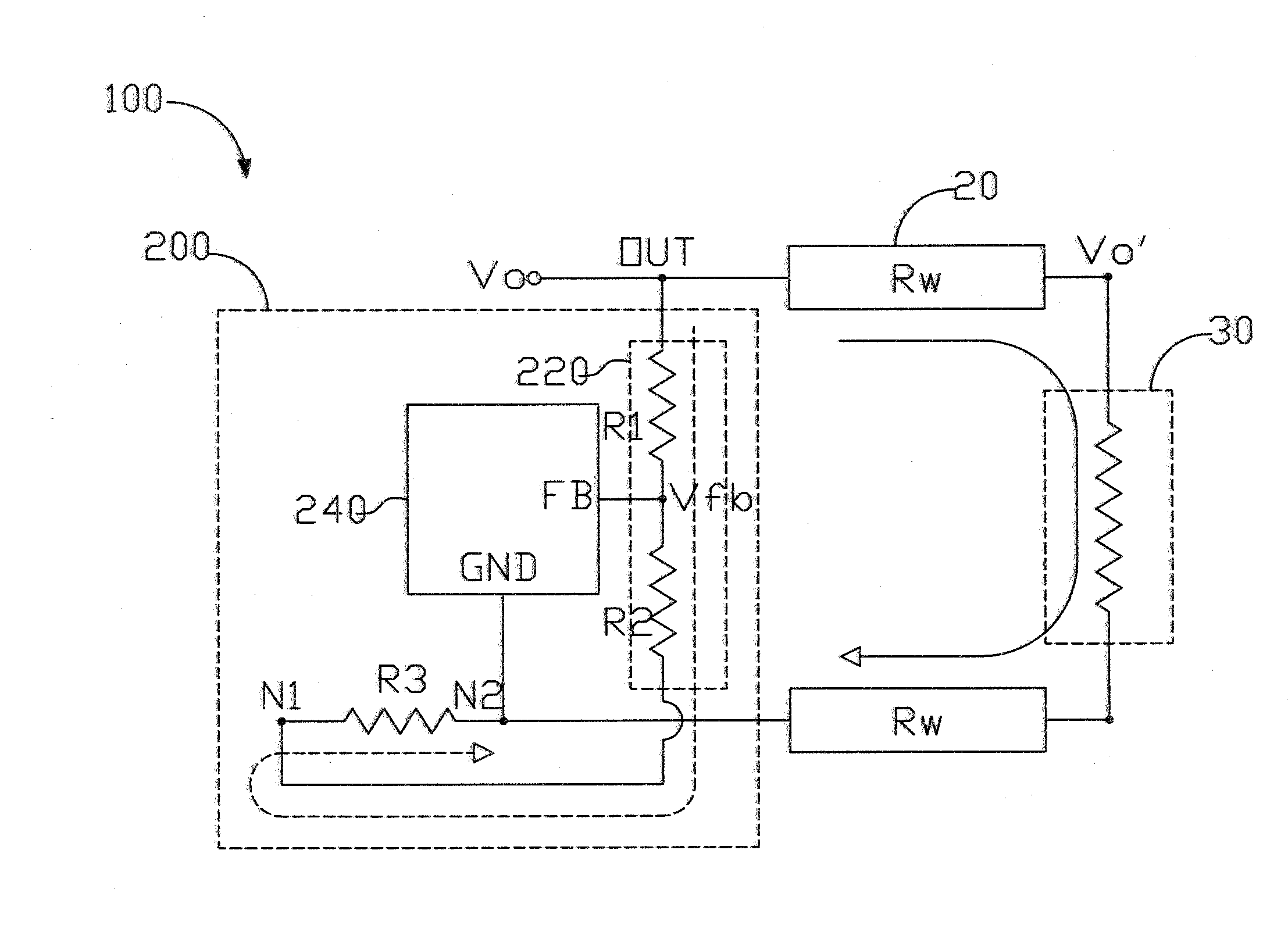
[0020]A main feature of the present invention is to couple a compensation resistor to the power wire for sensing the current on the power wire and use the compensation resistor to enhance the level of the feedback signal so as to compensation the voltage drop on the power wire.

[0021]FIG. 3 is a schematic view showing a power control circuit 200 with the function of wire compensation in accordance with a preferred embodiment of the present invention. The power control circuit 200 is applied in a power converter 100 to control the output of the power converter 100. The output voltage Vo of the power converter 100 is supplied to a load 30 through a power wire 20.

[0022]As shown, the power control circuit 200 has a feedback circuit 220, a controller 240, and a compensation resistor R3. The feedback circuit 220 is utilized for detecting the output voltage Vo of the power converter 100 and generates a feedback signal Vfb accordingly. The controller 240, which may be formed on a chip, is ut...


PUM


Abstract

A power control circuit with wire compensation is provided. The power control circuit is applied in a power converter, which has an output coupled to a load through a power wire. The power control circuit has an adaptive sensing circuit and a controller. The adaptive sensing circuit is utilized for detecting an output voltage of the power converter and a current on the power wire and generating a feedback signal according to the output voltage and the current on the power wire. The controller is utilized for adjusting a level of the output voltage according to the feedback signal.

Description

REFERENCE TO RELATED APPLICATIONS[0001]This Application is being filed as a continuation-in-part of patent application Ser. No. 12 / 585,265, filed 10 Sep. 2009, currently pending.BACKGROUND OF THE INVENTION[0002](1) Field of the Invention[0003]This invention relates to a power control circuit, and more particularly relates to a power control circuit for wire compensation and a compensation method for compensating voltage drop on a power wire.[0004](2) Description of the Prior Art[0005]FIG. 1 is a circuit diagram of a typical buck converter 10 which supplies electric power to a load 30 through a power wire 20. To stabilize the level of output voltage Vo, the buck converter 10 has a feedback circuit 12 and a controller 14 for performing feedback control on the output voltage Vo. The feedback circuit 12 is composed of two serially connected resistors and is utilized for detecting the level of the output voltage Vo for generating a feedback signal Vfb accordingly. The controller 14 recei...

Claims


Application Information

Patent Timeline
IPC IPC(8): G05F1/10
CPCG05F1/573H02M2001/0025H02M3/156H02J7/0073H02J7/0071H02M1/0025
Inventor TING, MING CHIANGCHIANG, CHUN-TELIU, CHIN MINGLIU, KER CHENG
Owner NIKO SEMICON
Why Eureka
Try Eureka