
System and methods for lighting and heat dissipation

a technology of heat dissipation and system, applied in the field of lighting devices, can solve the problems of affecting the performance of potential users, heating, and affecting the efficiency of lighting, so as to improve the combination of convenience and utility, increase the achievable productivity and economic efficiency, and improve the effect of efficiency

Inactive Publication Date: 2011-02-17
CHAKRAVARTY JYOTIRMOY +1
View PDF3 Cites 53 Cited by
  • Summary
  • Abstract
  • Description
  • Claims
  • Application Information

AI Technical Summary

Benefits of technology

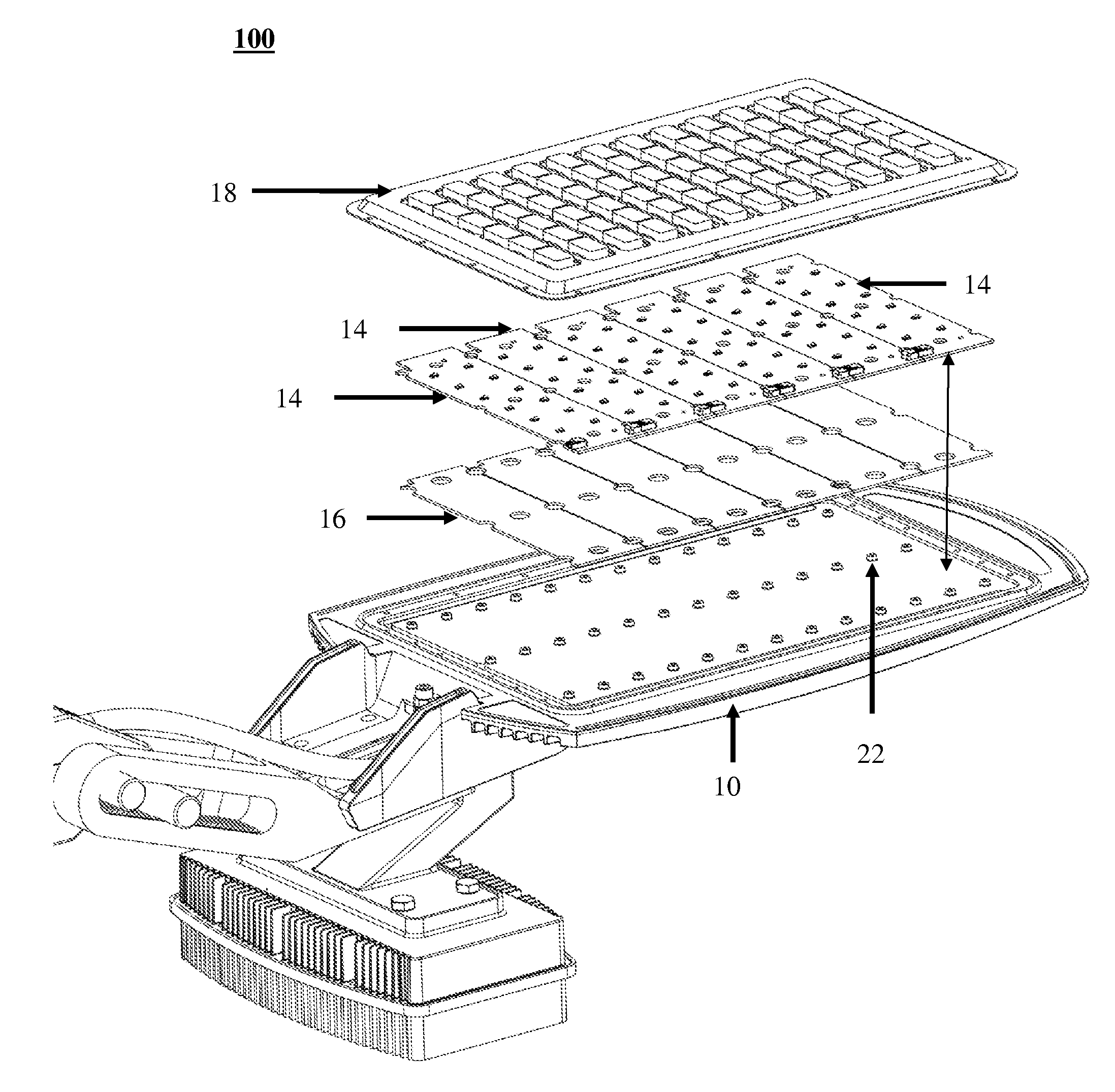
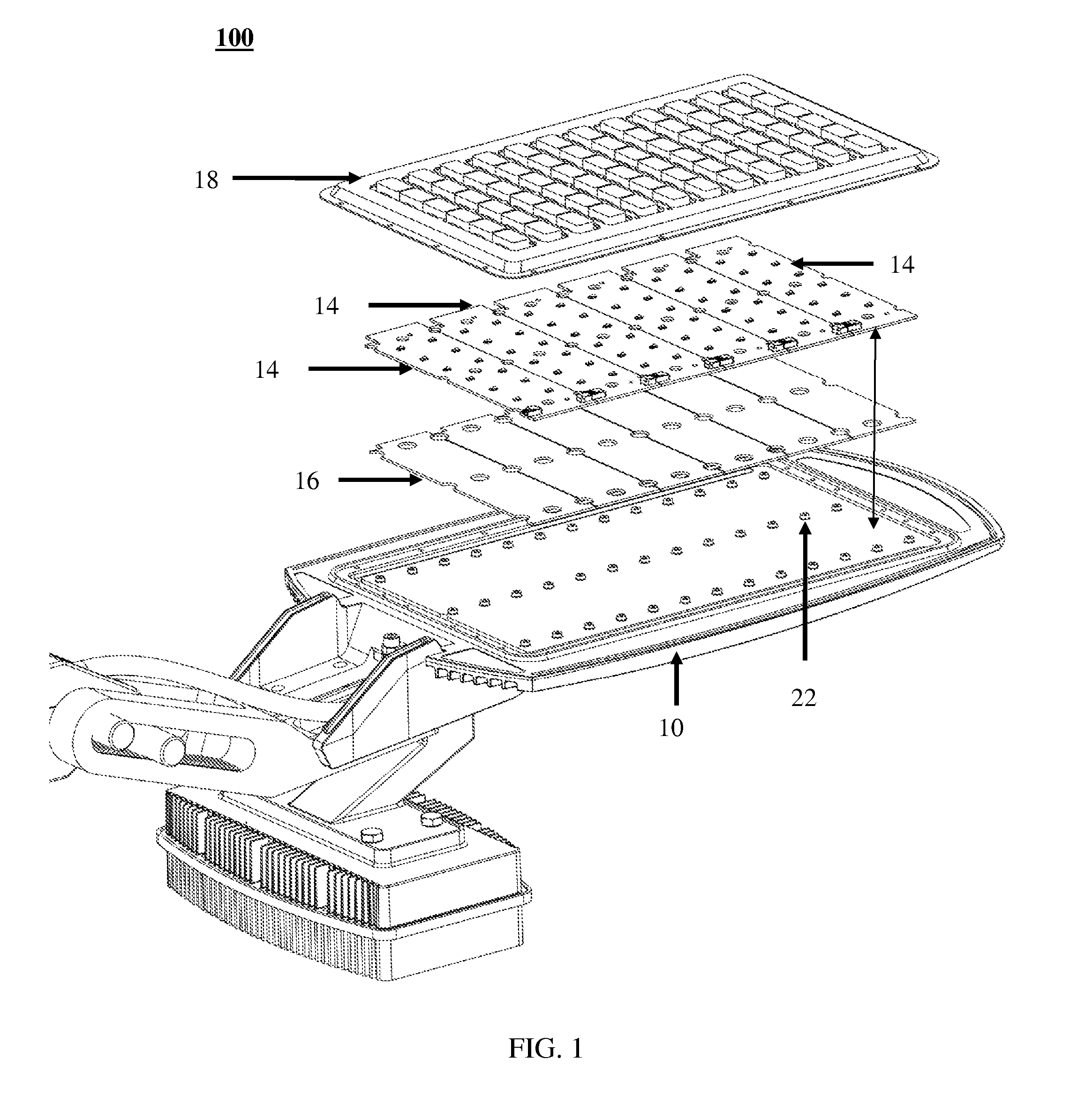
[0011]In view of the foregoing disadvantages inherent in the prior arts, the general purpose of the present invention is to provide an improved combination of convenience and utility, to include the advantages of the prior art, and to overcome the drawbacks inherent in the prior art. Therefore, the task of the inventions is to increase the achievable productivity and its economic efficiency.
[0012]The present invention provides an effective system and method for maximizing heat dissipation from the LED junction and eliminating air pockets within the fixture in an environmentally safe, convenient, and cost effective manner; to include advantages of the existing system and methods, and to overcome the drawbacks inherent therein.
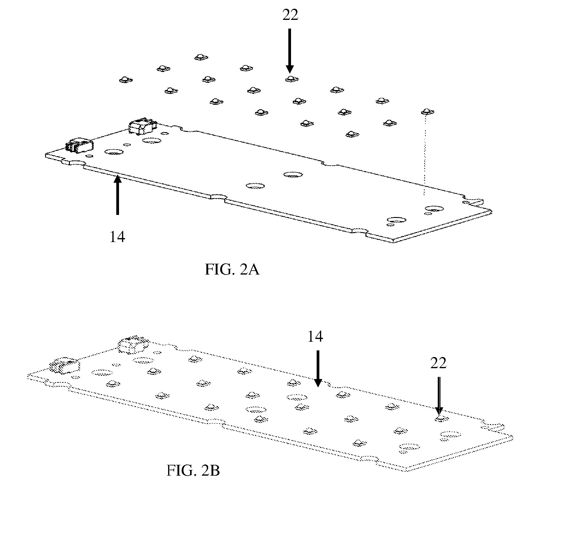
[0013]In one aspect, a system for lighting and heat dissipation of the present invention comprises: an uni-body fixture adapted to increase a heat dissipation surface area; atleast a metal PCB housing configured to house a pluralities of LEDs with zero air-gaps; and atleast a heat pad capable of mounting the metal PCB housing at a first face, wherein a plurality of tapered and directional heat sink fins adapted longitudinally across a length of an upper face of the uni-body fixture for fastest heat dissipation from atleast a LED junctions to the atmosphere. The uni-body fixture, metal PCB housing, and the heat pad constitute a light unit for providing a uniform high intensity light. A power supply unit having an independent heat sink surface area for heat dissipation is adapted to prevent heat contribution from the power supply unit to the light unit.
[0016]Through some very unique methods, it is ensured that the junction temperature of the LEDs is kept well below its rated temperature at all times. Apart from the fact that these methods of efficient heat management help in sustaining the life of the LEDs, they also allow for the LEDs to de lit at higher currents and thereby making the lamp even more cost effective and energy efficient.

Problems solved by technology

The predicted life of LED's are about 60,000 hours, however, LED's will lose their brightness and fail if the junction temperatures exceed the rated temperatures.
For the past many years the benefits of power efficiency in high power LED lights has been accepted however, the product cost has been the driving de-motivator for potential users.
Further, heat dissipation and its management on the fixture level is one of the biggest challenges that the LED lighting industry faces today and its success conclusively decides the success of the product itself.
The features of the conventional lighting and heat dissipation techniques, disclose a complex design and bulky structural indices that hinder their performance.
Many such techniques are too complex for reliable operation and fail to provide efficient means to maximizing heat dissipation from the LED junction and eliminating air pockets within the fixture, which may become highly damaging to the life of the LEDs.
No such system or technique is available in the commercial market at the present time which is capable of providing efficient means to maximizing heat dissipation from the LED junction and eliminating air pockets within the fixture.

Method used


Image

  • System and methods for lighting and heat dissipation
  • System and methods for lighting and heat dissipation
  • System and methods for lighting and heat dissipation

Examples


Embodiment Construction

[0029]The exemplary embodiments described herein detail for illustrative purposes are subject to many variations and structure and design. It should be emphasized, however that the present invention is not limited to a particular system and methods for lighting and high efficiency heat dissipation as shown and described. Rather, the principles of the present invention can be used with a variety of lighting and high efficiency heat dissipation configurations and structural arrangements. It is understood that various omissions, substitutions of equivalents are contemplated as circumstances may suggest or render expedient, but the present invention is intended to cover the application or implementation without departing from the spirit or scope of the it's claims.

[0030]In the following description, for purposes of explanation, numerous specific details are set forth in order to provide a thorough understanding of the present invention. It will be apparent, however, to one skilled in th...


PUM

PropertyMeasurementUnit
Temperatureaaaaaaaaaa
Fractionaaaaaaaaaa
Angleaaaaaaaaaa

Abstract

A system for lighting and heat dissipation of the present invention, comprises: an uni-body fixture adapted to increase a heat dissipation surface area; atleast a metal PCB housing configured to house a pluralities of LEDs with zero air-gaps; and atleast a heat pad capable of mounting the metal PCB housing at a first face, wherein a plurality of tapered and directional heat sink fins adapted longitudinally across a length of an upper face of the uni-body fixture for fastest heat dissipation from atleast a LED junctions to the atmosphere. A power supply unit having an independent heat sink surface area is adapted for heat dissipation to prevent heat contribution from the power supply unit to the light unit.

Description

CROSS-REFERENCE TO RELATED APPLICATION[0001]This non-provisional patent application claims priority from the U.S. provisional patent application Ser. No. 61 / 232,972 filed on Aug. 11, 2010, the content of which is incorporated herein by reference.FIELD OF THE INVENTION[0002]The present invention relates generally lighting devices, and more particularly, to system and methods for lighting and high efficiency heat dissipation in a low cost, convenient, environmentally safe, and cost effective manner.BACKGROUND OF THE INVENTION[0003]The purpose of changing over to newer lighting technology such as high power LED lamps is to get longer life and lower power consumption for the required luminary brightness at a cost that has a reasonable payback period. High power light emitting diode (LED) technology provide all the stated benefits when tested individually, however, the key to realizing benefits from a multiple LED lamp depends upon the configuration or design of the fixture.[0004]A key f...

Claims


Application Information

Patent Timeline
IPC IPC(8): F21S4/00F21V29/00H05K13/00B23P15/26
CPCF21V29/004F21Y2101/02F21V23/023Y10T29/4935F21V29/507F21V29/763Y10T29/49002F21Y2105/001F21Y2105/10F21Y2115/10
Inventor CHAKRAVARTY, JYOTIRMOYKUMAR, PRASHANT
Owner CHAKRAVARTY JYOTIRMOY
Learn More