Systems and methods for exhaust gas recirculation

a technology of exhaust gas recirculation and system, applied in the direction of machines/engines, electric control, combustion air/fuel air treatment, etc., can solve the problems of reducing the performance of the engine, limiting the above described approach, and not achieving uniform mixing to all cylinders of the engine, so as to achieve uniform egr distribution

Inactive Publication Date: 2011-02-24
GENERAL ELECTRIC CO
View PDF33 Cites 64 Cited by
  • Summary
  • Abstract
  • Description
  • Claims
  • Application Information

AI Technical Summary

Benefits of technology

[0007]In this way, it is possible to provide uniform EGR distribution to all engine cylinders, even with varying inlet air and EGR flow to the engine.

Problems solved by technology

However, the inventor herein has identified limitations to the above described approach.
For example, based on the particular spacing between locations at which EGR is introduced, the number of donor cylinders, and / or the firing order of the engine, the above described approach may not achieve uniform mixing to all cylinders of an engine.
Uneven mixing of EGR gases may degrade engine performance and lead to subsequent increased engine emissions.

Method used


Image

  • Systems and methods for exhaust gas recirculation
  • Systems and methods for exhaust gas recirculation
  • Systems and methods for exhaust gas recirculation

Examples


Embodiment Construction

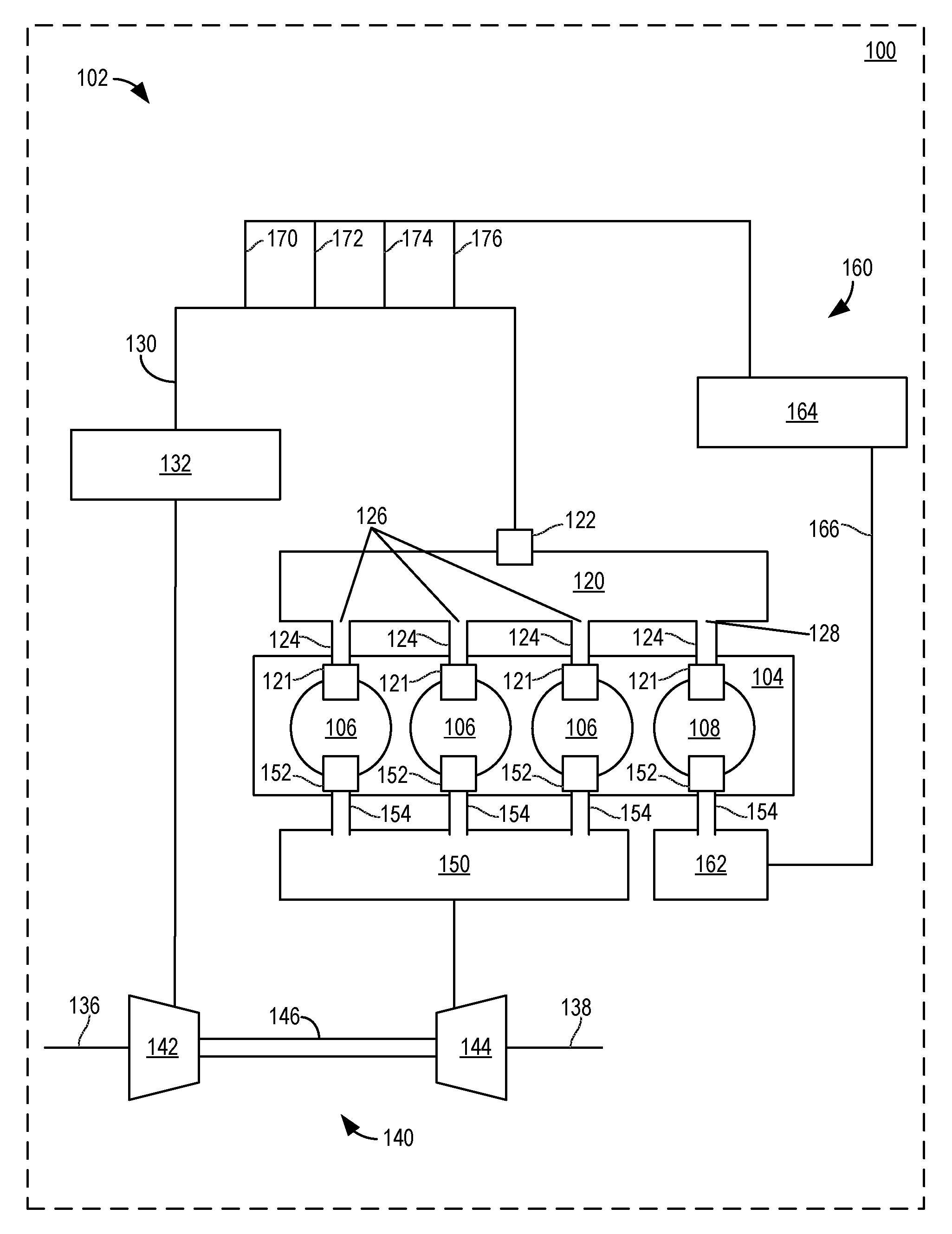
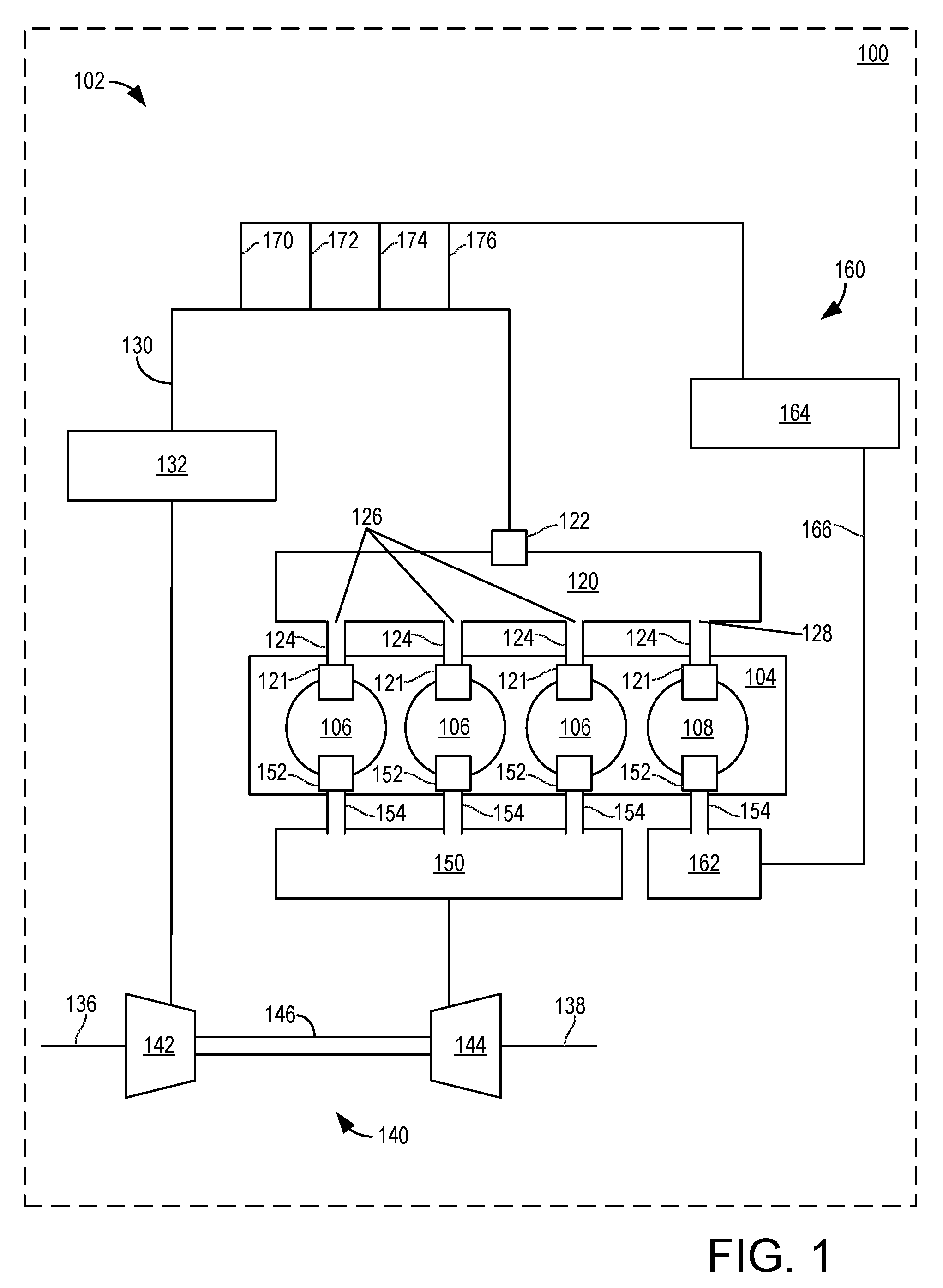
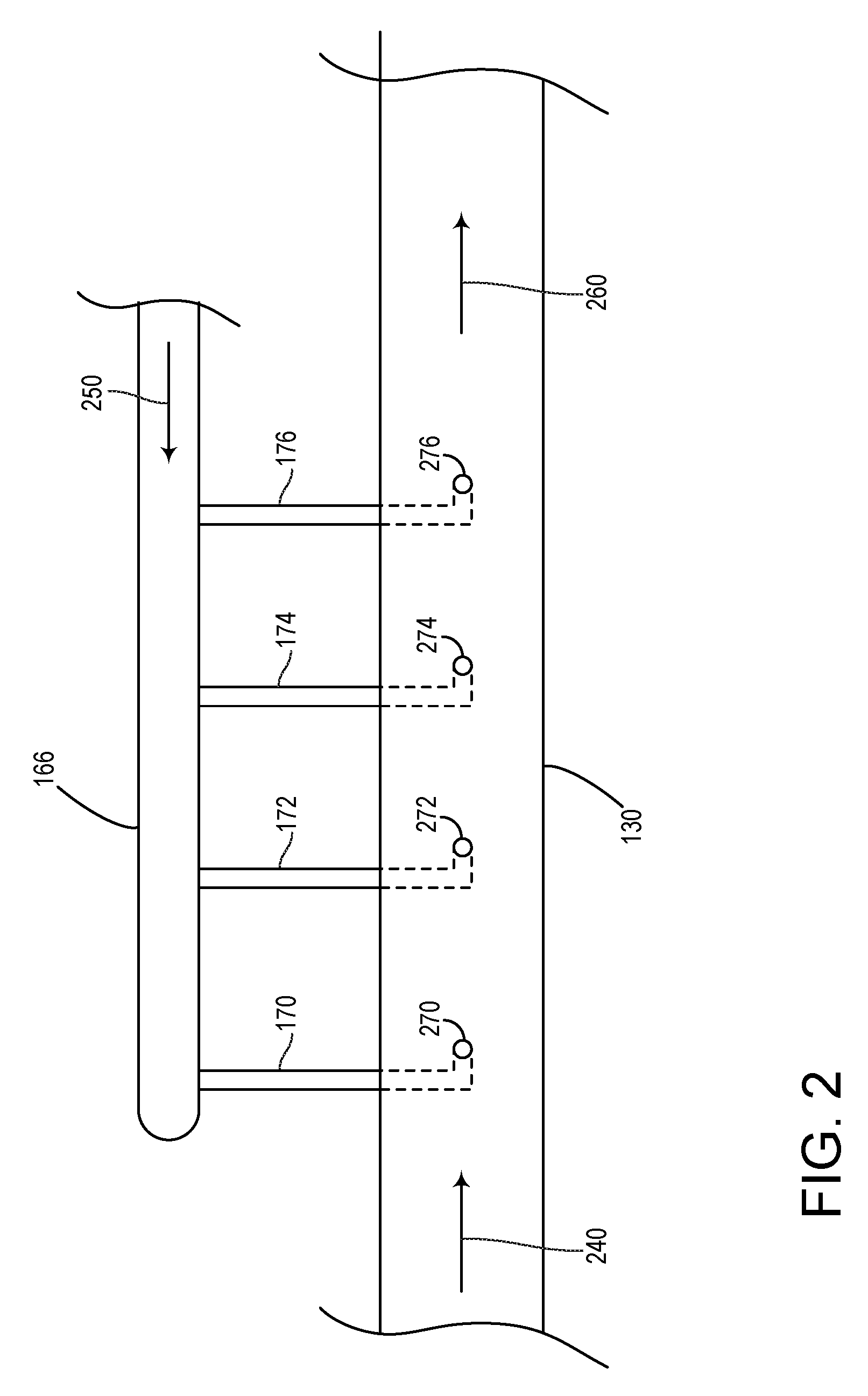
[0013]The systems, devices and approaches disclosed and described below outline various examples of introducing EGR gas in an intake passage of an engine system via multiple EGR inlets. The location of the EGR inlets, as well as the spacing, size and shape of the EGR inlets in relation to each other and various engine elements and components may lead to various improvements in EGR gas mixing. Such an approach is particularly advantageous in engines having a plurality of cylinders with one or more donor cylinders dedicated to EGR, such as for engines in locomotive, marine, stationary power plant, and / or Off-Highway Vehicle (OHV) applications.

[0014]FIG. 1 shows an example engine system 102 coupled in a device 100. In one example, device 100 may be a locomotive. However, as noted above, device 100 may alternatively be a ship / marine vessel, stationary power plant, OHV, or other devices.

[0015]As one example, the illustrated configuration of engine system 102 includes an engine 104, an in...


PUM


Abstract

Exhaust gas recirculation systems and methods related to internal combustion engines are provided. In one embodiment, a system comprises an engine having at least a first cylinder group and a second cylinder group, with at least one cylinder in each cylinder group, an intake manifold having an inlet and a first outlet coupled to the first cylinder group and a second outlet coupled to the second cylinder group, an intake passage coupled to the intake manifold inlet, and first and second exhaust manifolds coupled to the first and second cylinder groups, respectively. An exhaust gas recirculation system is further coupled between the second exhaust manifold and the intake passage, and has a number of openings positioned within the intake passage, the number of openings equal to or greater than a number of cylinders having an intake event between successive exhaust events occurring in the second cylinder group.

Description

FIELD[0001]The subject matter disclosed herein relates to exhaust gas recirculation (EGR) systems and methods, and more particularly to the introduction of the EGR gas into an engine intake.BACKGROUND[0002]Engines may utilize recirculation of exhaust gas from the engine exhaust system to the engine intake system, a process referred to as Exhaust Gas Recirculation (EGR), to reduce regulated emissions and / or improve fuel economy.[0003]In one approach, one or more cylinders are dedicated to generating EGR gasses delivered to the intake, where such cylinders may be referred to as donor cylinders. One example of such an approach is described in U.S. Pat. No. 4,249,382 to Evans et al. where only a portion of the pistons of an engine driven within the respective cylinders thereof will recirculate exhaust gas into the inlet manifold. In this example, as shown in FIG. 1 of Evans, the EGR gasses are introduced into a plurality of inlets in the intake manifold.BRIEF DESCRIPTION OF THE INVENTIO...

Claims


Application Information

Patent Timeline
Patent Type & Authority Applications(United States)
IPC IPC(8): F02B33/44F02M25/07
CPCF02B29/0437F02D41/0065F02M25/0707F02M25/0722Y02T10/47F02M25/0749F02M25/0751F02M35/10222Y02T10/146F02M25/0731F02M26/43F02M26/05F02M26/19F02M26/28F02M26/44Y02T10/12Y02T10/40
Inventor YAGER, JAMES HENRY
Owner GENERAL ELECTRIC CO
Why Eureka
Try Eureka