
Method and apparatus for optimized combustion in an internal combustion engine utilizing homogeneous charge compression ignition and variable valve actuation

a technology of compression ignition and combustion engine, applied in the direction of valve drives, electric control, machines/engines, etc., can solve the problems of excessive compression ratio, difficult control, and significant challenge in avoiding high cost and complexity

Inactive Publication Date: 2006-07-06
DELPHI TECH INC
View PDF5 Cites 86 Cited by
  • Summary
  • Abstract
  • Description
  • Claims
  • Application Information

AI Technical Summary

Benefits of technology

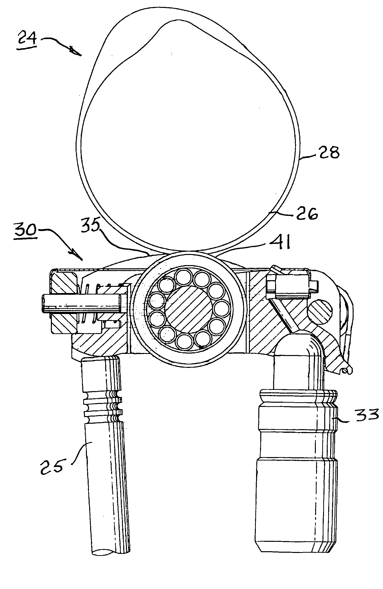
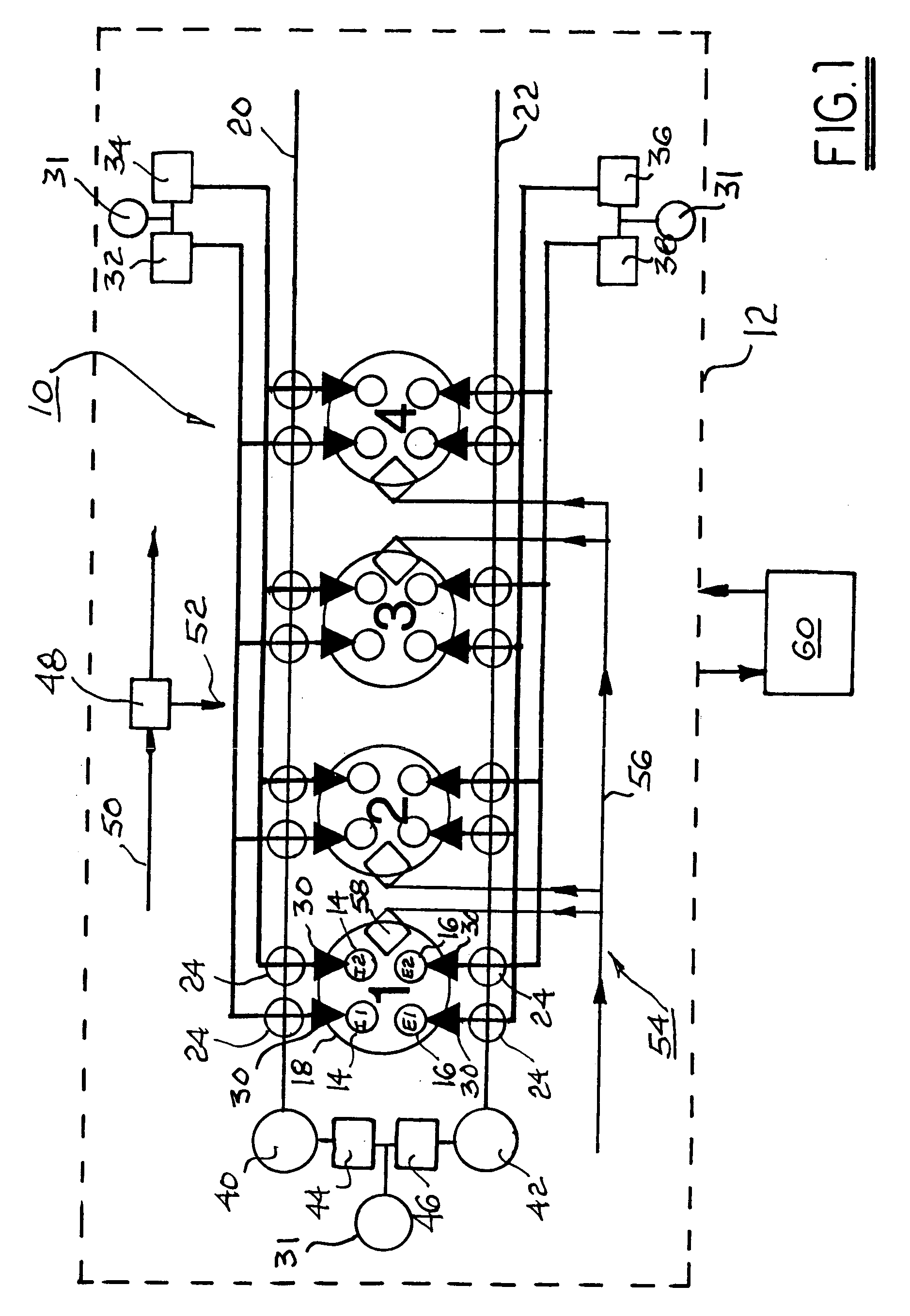
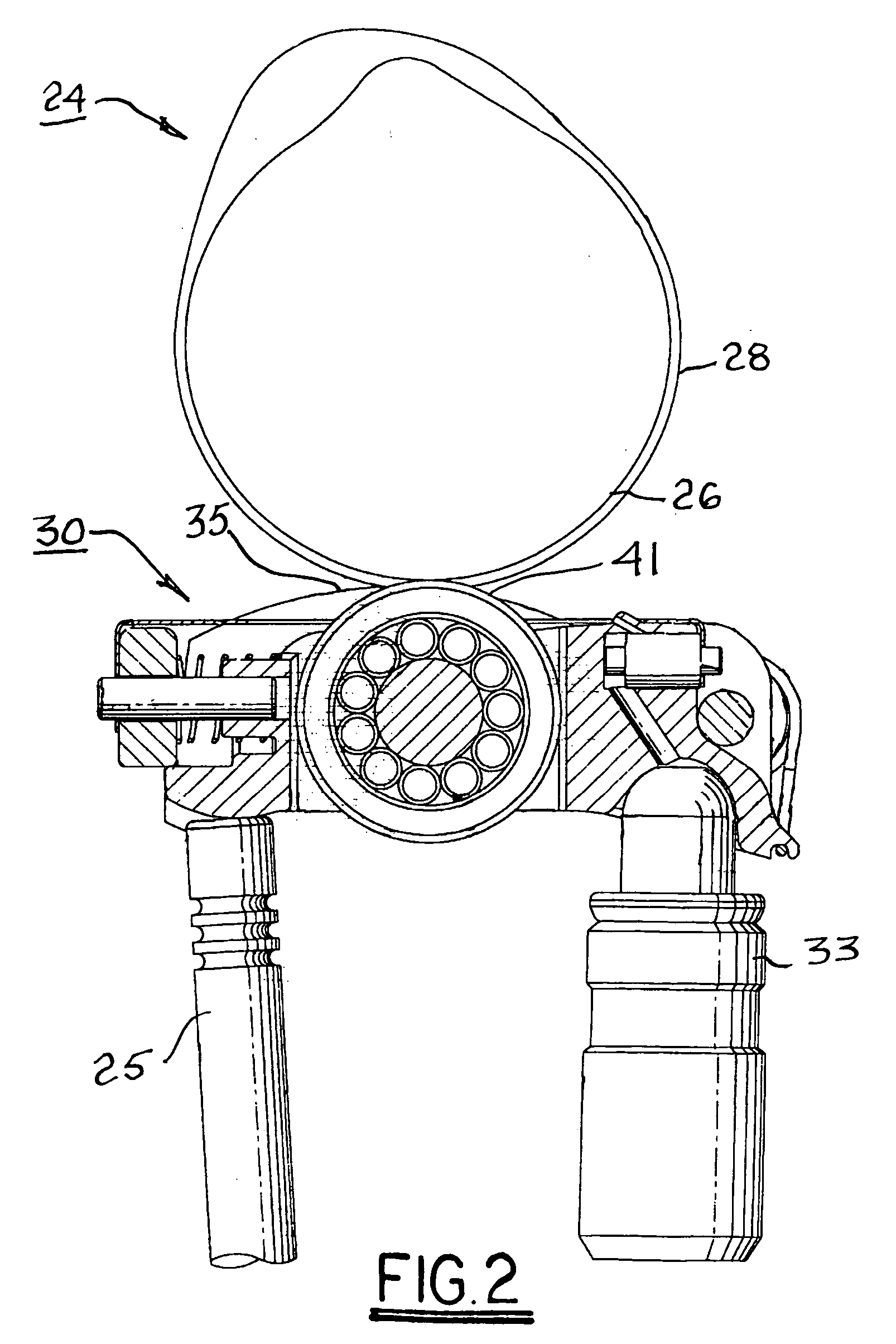
[0028] Briefly described, a valvetrain system mechanization for a CI engine includes two engine intake valves and two engine exhaust valves per cylinder. The valves are operated by dual overhead camshafts (intake and exhaust) having “three-lobe” two-step cams for each valve wherein a central lobe is a high-lift or low-lift lobe and a pair of lateral lobes outboard of the central lobe are correspondingly low-lift or high-lift lobes. The lift of the high-lift lobe is greater than the lift of the low-lift lobes at any cam position. A conventional two-step roller finger follower (RFF) for varying selectively the lift of a valve between high-lift and low-lift by selective application or withholding of high-pressure oil to each RFF is disposed for each intake valve and each exhaust valve between the cam lobes and the valve stem.

Problems solved by technology

These combustion processes require special in-cylinder conditions, operate in critical ranges, and generally are difficult to control.
Avoidance of high cost and complexity is a significant challenge for many advanced engine concepts.
Because combustion initiation is chemically-kinetically controlled, one problem of HCCI systems is that parameters other than fuel injection timing (as for conventional diesel engines) must be controlled in order to control combustion initiation.
However, once warmed up, such compression ratios are excessively high and reduce thermodynamic efficiency due to high heat losses.
In other words, higher CR demands a more massive, heavy, and expensive engine than lower CR.
Prior art external EGR systems, wherein exhaust gas is metered from the exhaust manifold into the intake manifold, offer the advantage of cooling the exhaust gas for reduced NOx, but these systems are bulky, expensive, and slow to respond.
Swirl can be produced in the prior art by swirl ports, but such devices limit full-load airflow and engine power.
PDA systems are used widely in the prior art but they suffer from deposit accumulation downstream of the PDA device and may introduce a flow loss due to shafts or other mechanisms blocking airflow.
Heating the catalyst more quickly shortens the time to catalyst light off and thereby shortens the period of uncatalyzed emissions.
Another problem with CI combustion in general, and HCCI combustion in particular, is the extremely low exhaust temperatures that are typically encountered for warmed-up conditions.
Exhaust temperatures below 150° C. are known to limit catalyst conversion efficiency.
Some CI engines incorporate a throttle to reduce trapped air mass but throttling reduces engine efficiency.
If the intake plenum is charged with fresh air plus conventionally-recirculated exhaust gas, several combustion cycles may be necessary to purge the EGR from the system, and this can contribute to poor or delayed torque response.

Method used


Image

  • Method and apparatus for optimized combustion in an internal combustion engine utilizing homogeneous charge compression ignition and variable valve actuation
  • Method and apparatus for optimized combustion in an internal combustion engine utilizing homogeneous charge compression ignition and variable valve actuation
  • Method and apparatus for optimized combustion in an internal combustion engine utilizing homogeneous charge compression ignition and variable valve actuation

Examples


Embodiment Construction

[0053] In the following discussion, the mechanisms and strategies for varying valve lift and valve timing for a compression-ignited (CI) engine in accordance with the invention are presented in the context of light duty engines which may be operated in either conventional diesel ignition (DI) mode or homogeneous charge compression ignition (HCCI) mode, or combinations thereof depending upon engine speed and load. However, it should be understood that such novel mechanisms and strategies may also be applied to medium duty and heavy duty CI-type engines. Further, engines comprehended by the invention may be hybrids that utilize compression ignition under some operating conditions and spark ignition under other operating conditions. Further, such engines are not limited to diesel fuel and may be fueled by other fuels such as gasoline and / or specialty fuels. The term “specialty fuels” as used herein is defined to include blended fuels, as needed, to provided the desired autoignition pro...


PUM


Abstract

A valvetrain system mechanization for an internal combustion engine using compression ignition, including homogeneous charge compression ignition, having two intake and one or more exhaust valves per cylinder. The valves are operated by dual overhead camshafts having two-step cams. The intake and exhaust camshafts are provided with phasers for varying the opening and closing of the intake and exhaust valves. A two-step roller finger follower is disposed for each valve between the cam lobes and the valve stem. The two sets of intake and exhaust valves are controlled by separate oil control valves. Swirl of gases may be introduced by mismatching the lifts of the valves. The valve opening times, closing times, lifts, fuel injection, compression ratio, and exhaust gas recirculation may be varied to optimize combustion conditions for a range of engine operating modes.

Description

TECHNICAL FIELD [0001] The present invention relates to combustion in internal combustion engines; more particularly, to a variable valve actuation (VVA) and phasing system for a compression-ignited engine; and most particularly, to a simple method and apparatus incorporating variable valve actuation and camshaft phasing for optimizing and controlling compression-ignited combustion, and especially homogeneous charge compression ignition (HCCI) (also known as controlled autoignition) combustion, to reduce emissions of nitrogen oxides (NOx) and particulate matter (PM), improve engine performance, and increase fuel efficiency over a range of engine operating modes. BACKGROUND OF THE INVENTION [0002] Advanced combustion processes are being developed in the engine combustion arts to reduce emissions of NOx and PM from both spark-ignited (SI) and compression-ignited (CI) engines, especially light-duty automotive engines. As used herein, “spark-ignited” and “spark ignition” refers to any i...

Claims


Application Information

Patent Timeline
Patent Type & Authority Applications(United States)
IPC IPC(8): F01L1/34
CPCF01L1/08F01L1/185F01L1/2405F01L13/0036F01L2105/00F01L2820/01F02B1/12F02B31/02F02B37/12F02D13/0207F02D13/0257F02D13/0261F02D41/3035F02D2013/0292F02D2041/001Y02T10/128Y02T10/146Y02T10/18F01L2001/186F01L2305/00Y02T10/12F02B31/085
Inventor SELLNAU, MARK C.DINGLE, PHILIP J. G.
Owner DELPHI TECH INC
Learn More