Prediction and estimation of the states related to misfire in an HCCI engine

a technology of misfire and prediction, applied in the field of methods of predicting misfire, can solve problems such as stalling of engine operation

Inactive Publication Date: 2011-11-03
ROBERT BOSCH GMBH
View PDF1 Cites 38 Cited by
  • Summary
  • Abstract
  • Description
  • Claims
  • Application Information

AI Technical Summary

Benefits of technology

[0012]The method of the present application uses a modified Arrhenius integral threshold, a novel recursive mass flow equation to capture the effect of feedback from cycle-to-cycle and couple it with a thermodynamics model to capture the effect of partly burned fuel and misfires. Also presented is a model to predict the amount of fuel that is used if a misfire occurs. For illustration purposes, the strategy / method in the present application is compared to a high-fidelity model for misfire, presented in K. L. Knierim, Sungbae Park, J. Ahmed, A. Kojic, I. Orlandini and A. Kulzer: “Simulation of misfire and strategies for misfire recovery of gasoline HCCI,” Proceedings of the 2008 American Control Conference, pages 3947-3952, 2008. In “Simulation of misfire and strategies for misfire recovery of gasoline HCCI,” a model was presented which used a simplified chemical mechanism for the oxidation of iso-octane and n-heptane coupled with an airflow model, and the chemical kinetics were modeled using a detailed simulation software that was able to capture the effect of partly burned fuel or misfires.

Problems solved by technology

HCCI operation at low loads is beneficial, but difficult due to the presence of combustion instabilities.
These instabilities cause the engine to misfire, thus stalling its operation.
However, applying the same strategy in case of misfire is detrimental to bringing the engine back to stable combustion, i.e., in case of misfire, instead of decreasing the amount of EGR, it is necessary to increase the amount of EGR to keep more thermal energy inside of the cylinder.

Method used


Image

  • Prediction and estimation of the states related to misfire in an HCCI engine
  • Prediction and estimation of the states related to misfire in an HCCI engine
  • Prediction and estimation of the states related to misfire in an HCCI engine

Examples


example simulation

[0076 Results for the Method

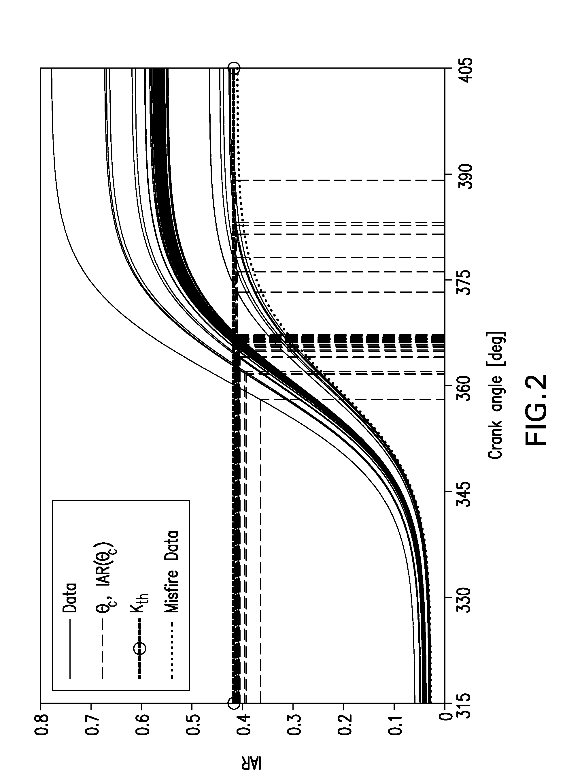
[0077]FIG. 4 shows the value of IAR with the parameters in Table 1 as a function of the crank angle in degrees. All curves represented on this figure are the result of a misfire in the first cycle (note that the value of IAR(θ)th during the nominal compression / expansion strokes). During the compression stroke in the trapping phase, the integrand of IAR takes on a highly positive value again and for some trajectories, combustion occurs in the trapping phase, where IAR(θ)≈Kth,2=0.5958. Lines denoted by reference character (B) in FIG. 4 are data points where a misfire occurred, but a combustion occurred in the trapping phase (recovery); lines denoted by reference character (R) in FIG. 4 are data points where a misfire occurred without a trapping phase combustion.

[0078]As described earlier, in case of misfire, instead of decreasing the amount of EGR, it is necessary to increase the amount of EGR to keep more thermal energy inside of the cylinder. The followin...


PUM


Abstract

A method for predicting and correcting an impending misfire in a homogeneous charge compression ignition (HCCI) engine includes: modeling HCCI engine operation in a nominal, steady-state operating region and in unstable operating regions bordering the steady-state operating region, using a zero-dimensional model; predicting an occurrence of an engine misfire based on the modeling of the HCCI engine operation; and providing a remedial corrective measure when an engine misfire is predicted. The remedial corrective measure includes one of: (a) late injection to avoid full combustion during a trapping cycle, and a reduction in amount of injected fuel to account for residual fuel of the previous cycle; or (b) earlier exhaust valve closing to trigger combustion of residual fuel within the trapping cycle, and a later injection and reduction of injected fuel to account for residual fuel of the previous cycle.

Description

BACKGROUND OF THE INVENTION[0001]1. Field of the Invention[0002]The present invention relates to a method of predicting a misfire before it occurs during operation of an HCCI engine so that preventive and / or remedial action may be taken.[0003]2. Description of Related Art[0004]Homogeneous charge compression ignition or HCCI is a combustion method that has been proposed for internal combustion engines. It is attractive in automotive applications, since HCCI can yield high efficiencies at partial loads (up to 30%) compared to a conventional spark ignited combustion. Furthermore, engines that run on HCCI also yield significantly reduced NOx emissions due to their low operating temperatures on an average. Some of these results have been reported. Essentially, HCCI involves a homogenized charge, which auto ignites due to compression within the combustion stroke. Thus, it combines the advantage of diesel-like combustion by including high compression ratios, while maintaining the low emiss...

Claims


Application Information

Patent Timeline
Patent Type & Authority Applications(United States)
IPC IPC(8): F02D28/00
CPCF02D41/1498F02D41/3029Y02T10/128F02N2300/2008G01M15/11F02D2200/1015Y02T10/12
Inventor CHATURVEDI, NALINMAYHEW, CHRISTOPHERPARK, SUNGBAEAHMED, JASIMKOJIC, ALEKSANDARSONG, HANHOCOOK, DAVIDKNIERIM, KARL LUKAS
Owner ROBERT BOSCH GMBH
Why Eureka
Try Eureka