Method and apparatus to operate a homogeneous charge compression-ignition engine

a compression ignition and engine technology, applied in the direction of electric control, machines/engines, output power, etc., can solve the problems of affecting combustion, reducing engine breathability, affecting combustion,

Active Publication Date: 2007-05-17
GM GLOBAL TECH OPERATIONS LLC
View PDF27 Cites 39 Cited by
  • Summary
  • Abstract
  • Description
  • Claims
  • Application Information

AI Technical Summary

Benefits of technology

[0014] The present invention uses engine control methodologies comprising variable valve actuation, fuel injection strategies, spark timing, and intake and coolant temperature control, to dynamically compensate for the effect of CCD on controlled auto-ignition combustion. Utilizing control logic to compensate for the effect of combustion chamber deposits to reduce combustion variability, which can be used in conjunction with other control functions and feedback loops in a known HCCI engine controller.

Problems solved by technology

This is primarily due to the combustion chamber deposits acting as an insulating layer on the combustion chamber surfaces, which affects combustion.
The result of the formation of the insulating layer includes a decrease in maximum and average heat flux away from the combustion chamber, a decrease in heat transfer to engine coolant, and a decrease in engine breathability, i.e. air flow, leading to a reduced volumetric efficiency.
Furthermore, the resultant effects include reduced engine power, a potential for increase in NOx emissions, and an increased likelihood of pre-ignition, or knock.
However, there is a limit at which an engine can be operated with a diluted mixture because of misfire and combustion instability as a result of a slow burn.
However, CCD properties and thickness are subject to change during engine operation.
This may not be possible in multi-cylinder engines equipped with conventional mechanical cam phasing systems (and not having individual cylinder VVA capability) that are not able to implement individual, cylinder-specific valve lift profiles and timings.

Method used


Image

  • Method and apparatus to operate a homogeneous charge compression-ignition engine
  • Method and apparatus to operate a homogeneous charge compression-ignition engine
  • Method and apparatus to operate a homogeneous charge compression-ignition engine

Examples


Embodiment Construction

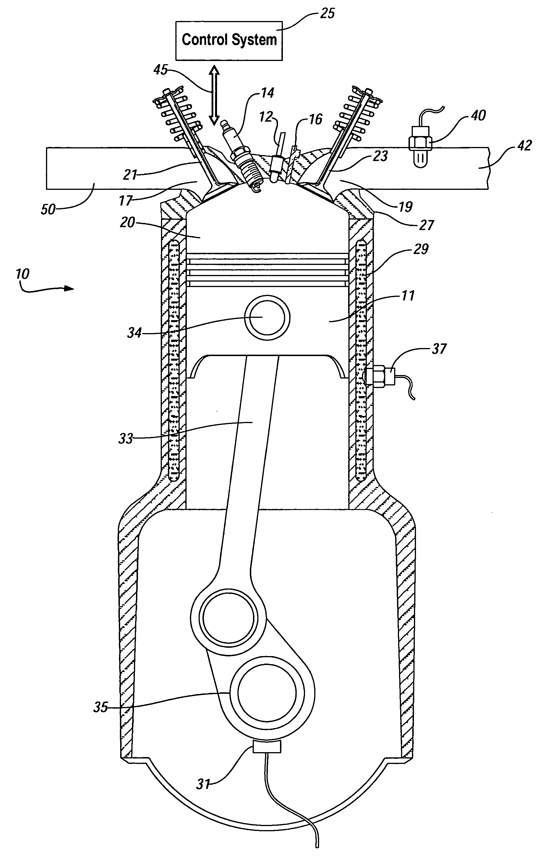
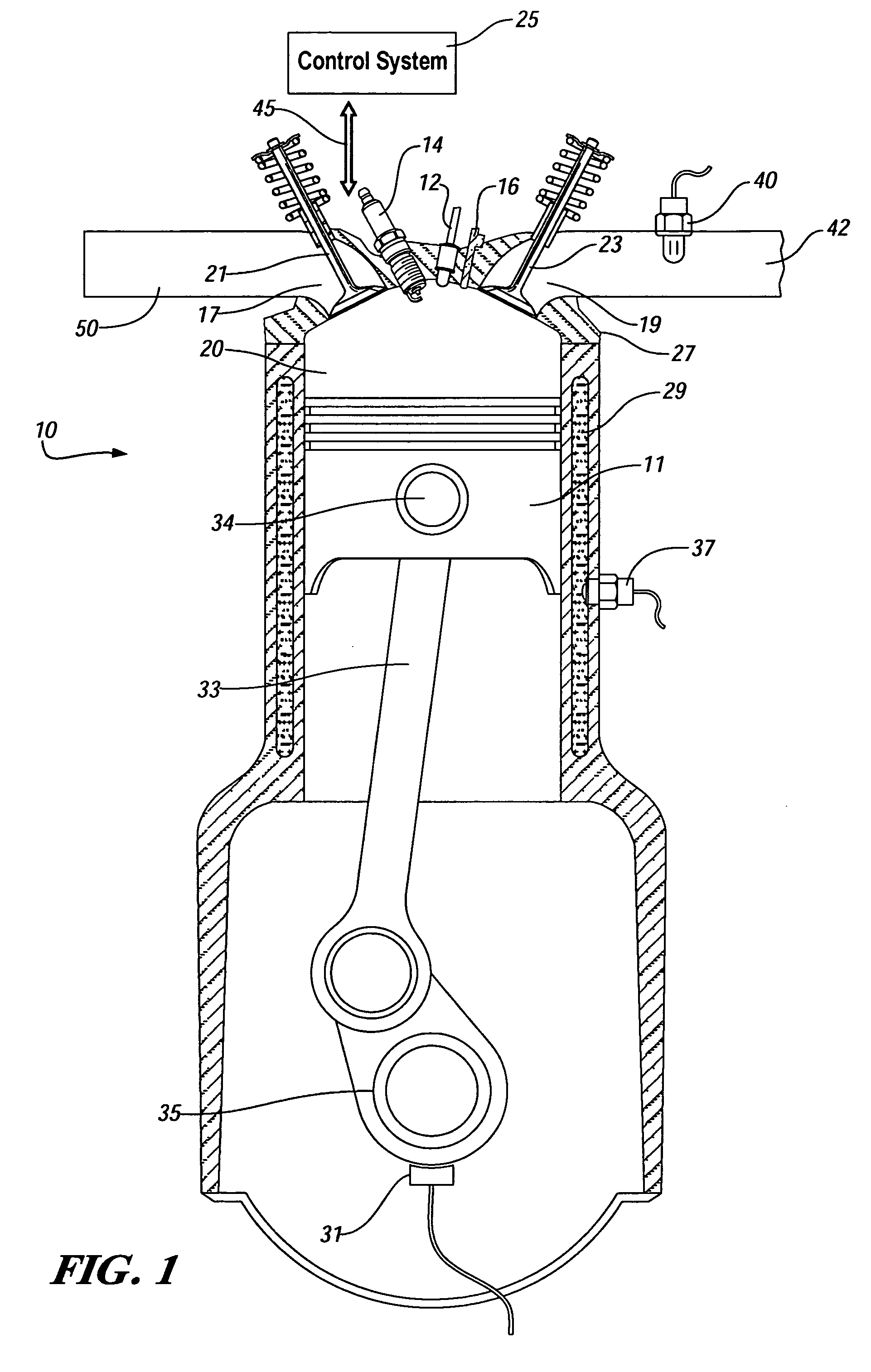
[0029] Referring now to the drawings, wherein the showings are for the purpose of illustrating the invention only and not for the purpose of limiting the same, FIG. 1 shows a schematic of an internal combustion engine 10 and control system 25 which has been constructed in accordance with an embodiment of the present invention. The embodiment as shown is applied as part of an overall control scheme to operate an exemplary multi-cylinder spark ignition, direct-injection, gasoline, four-stroke internal combustion engine adapted to operate under a controlled auto-ignition process, also referred to as homogenous-charge, compression-ignition (‘HCCI’).

[0030] The exemplary engine 10 comprises: a cast-metal engine block with a plurality of cylinders 13 formed therein, one of which is shown, and an engine head 27. Each cylinder 13 comprises a closed-end cylinder having a moveable, reciprocating piston 11 inserted therein. A variable volume combustion chamber 20 is formed in each cylinder, an...


PUM


Abstract

A method and apparatus for controlling engine operation to compensate for effects of combustion chamber deposits (CCDs) on combustion in a controlled auto-ignition engine is presented. Control methodologies comprise operation of variable valve actuation, fuel injection, spark timing, and intake air and coolant temperature to dynamically compensate for the effect of CCDs. A sensitivity to core gas temperature and chamber wall thermal conditions is shown, which is correlatable to in-cylinder CCD formation. Intake charge or coolant temperature control can be used to compensate for CCD effects. An engine control scheme relies upon a parametric input that quantifies instantaneous CCD formation in the combustion chamber. The result is further applicable to control pre-ignition in a conventional spark-ignition engine.

Description

CROSS-REFERENCE TO RELATED APPLICATIONS [0001] This application claims priority from U.S. Provisional Application No. 60 / 737,156, filed Nov. 16, 2005, entitled METHOD AND APPARATUS TO CONTROL COMBUSTION IN A HOMOGENEOUS CHARGE COMPRESSION-IGNITION ENGINE.TECHNICAL FIELD [0002] This invention pertains generally to internal combustion engine control systems, and more specifically to a method and apparatus to control operation of a homogeneous-charge compression-ignition engine. BACKGROUND OF THE INVENTION [0003] An internal combustion engine operating under various conditions can experience a build-up of combustion chamber deposits (‘CCD’), which comprise a deposition of products of the combustion process onto surfaces of the combustion chamber. The deposits are typically derived from fuels and fuel additives, lubricating oils and oil additives, and other elements, as is known. [0004] As deposits adhere to surfaces of the combustion chamber, thermal characteristics of the engine chang...

Claims


Application Information

Patent Timeline
Patent Type & Authority Applications(United States)
IPC IPC(8): F02B5/00F02M7/00
CPCF02B1/12F02B23/0672F02D13/0234F02D35/02F02D35/028F02D41/005F02D41/1467F02D41/3035F02D2041/001Y02T10/125Y02T10/128Y02T10/18Y02T10/12
Inventor KUO, TANG-WEINAJT, PAUL M.ENG, JAMES A.RASK, RODNEY B.
Owner GM GLOBAL TECH OPERATIONS LLC
Why Eureka
Try Eureka