
Control apparatus for an internal combustion engine capable of pre-mixed charge compression ignition

a control apparatus and internal combustion engine technology, applied in mechanical apparatus, electric control, machines/engines, etc., can solve problems such as temperature uniformity, achieve stable self-ignition combustion, reduce noise combustion noise, and increase temperature uniformity

Inactive Publication Date: 2008-09-09
TOYOTA JIDOSHA KK
View PDF32 Cites 40 Cited by
  • Summary
  • Abstract
  • Description
  • Claims
  • Application Information

AI Technical Summary

Benefits of technology

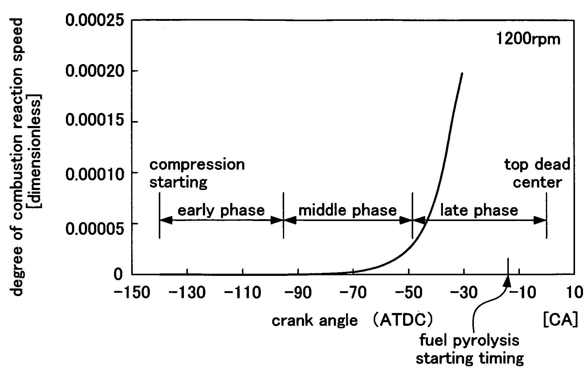
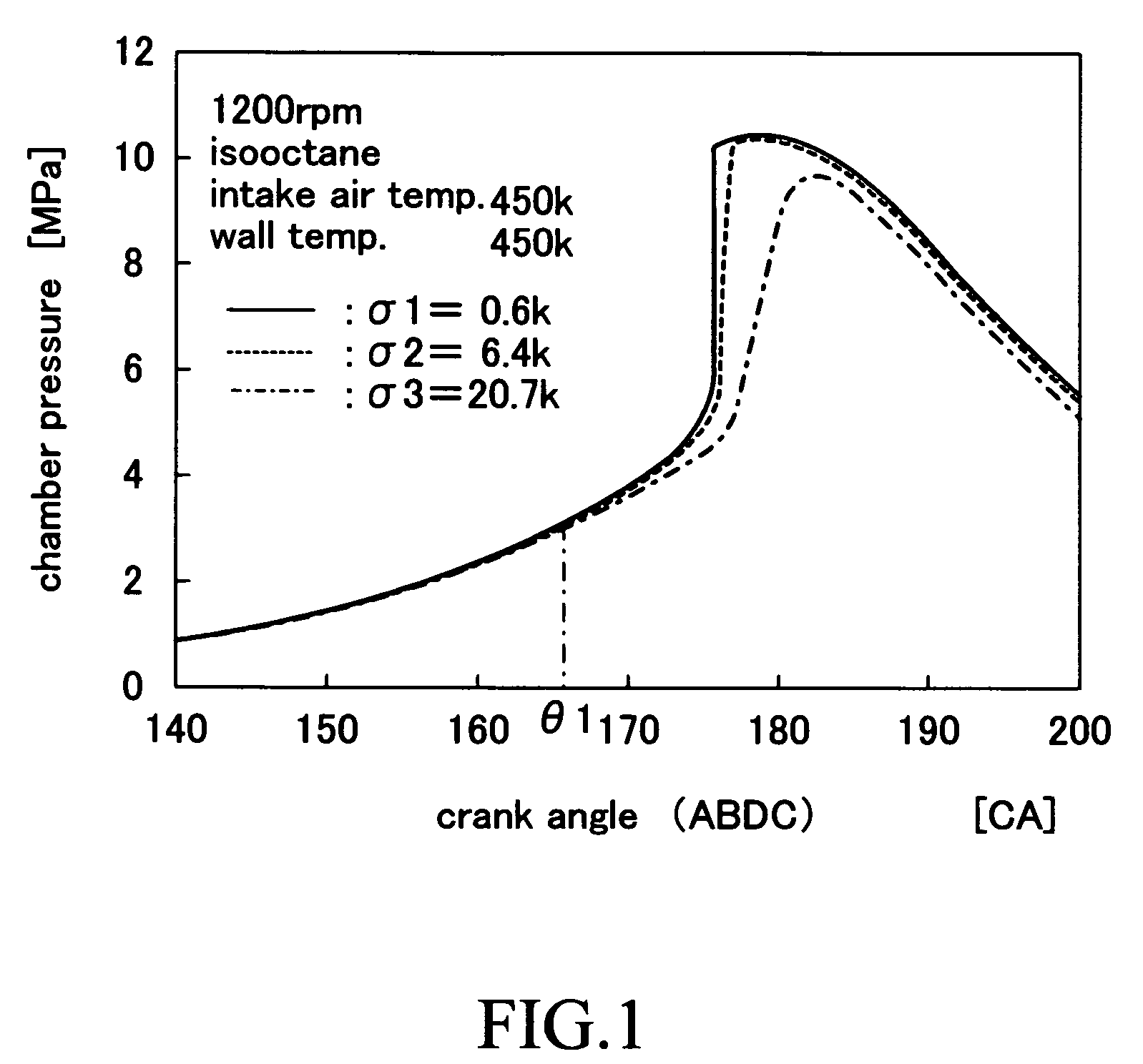
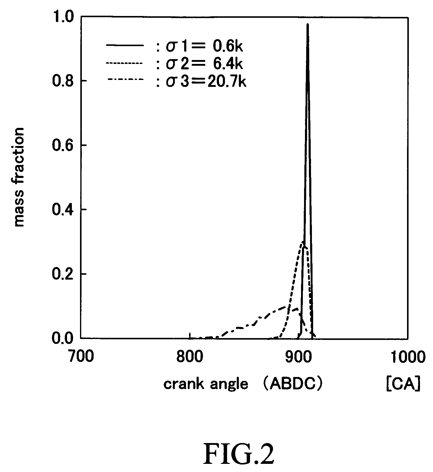
The present invention provides a control apparatus for an internal combustion engine that can modify self-ignition combustion by making the temperature un-uniformity of the air-fuel mixture gas at a fuel pyrolysis starting timing larger than the temperature un-uniformity of the air-fuel mixture gas obtained by simply compressing it during the compression stroke. This can be achieved by injecting high pressure fluid into the air-fuel mixture gas at a predetermined acting timing during the compression stroke. The enhanced temperature un-uniformity can lead to a reduction in pressure rising rate and combustion noise, and can also make the combustion reaction speed uneven between high and low temperature areas. The control apparatus can be used in an internal combustion engine with fuel injection and can be adjusted based on driving conditions and engine load.

Problems solved by technology

As a result, the temperature un-uniformity of the air-fuel mixture gas at the fuel pyrolysis starting timing which occurs just before the self-ignition timing is made larger than temperature un-uniformity of the same normally obtained only by simply compressing the air-fuel mixture gas during the compression stroke.

Method used


Image

  • Control apparatus for an internal combustion engine capable of pre-mixed charge compression ignition
  • Control apparatus for an internal combustion engine capable of pre-mixed charge compression ignition
  • Control apparatus for an internal combustion engine capable of pre-mixed charge compression ignition

Examples


first embodiment

[0139]FIG. 9 shows a schematic configuration of a system configured such that a control apparatus for an internal combustion engine according to a first embodiment of the present invention is applied to a pre-mixed (homogeneous) charge compression ignition (self-ignition or spontaneous ignition) 2-cycle internal combustion engine 10. The 2-cycle engine is an engine in which repeats an expansion (combustion and expansion) stroke, an exhaust stroke, a scavenging stroke, an intake (or charging stroke), and a compression stroke every 360° crank angle.

[0140]The pre-mixed charge compression ignition internal combustion engine 10 includes a cylinder block section 20 including a cylinder block, a cylinder block lower case, an oil pan, etc.; a cylinder head section 30 fixed on the cylinder block section 20; an intake system 40 for supplying air (new air) to the cylinder block section 20; and an exhaust system 50 for emitting exhaust gas from the cylinder block section 20 to the exterior of t...

second embodiment

[0186]A control apparatus for the internal combustion engine according to the second embodiment of the present invention will be described. The control apparatus according to the second embodiment differs from the first embodiment in that the second embodiment injects into the combustion chamber 25 high pressure hydrogen gas (or high pressure carbon monoxide gas) as the high pressure fluid, instead of the high pressure air. Thus, hereinafter, the description is made by focusing on this difference.

[0187]This control apparatus, as shown in FIG. 16, comprises a gas injection valve 81 in place of the air injection valve 38. The gas injection valve 81 is communicated with a gas accumulation tank 81a, a heat exchange unit 81b, a gas compressor (a gas compressing pump) 81c, and a gas tank 81d, in this order. The gas compressor 81c compresses hydrogen gas in the gas tank 81d in response to a driving signal, and then supplies the heat exchange unit 81b with the compressed hydrogen gas. The h...

third embodiment

[0198]A control apparatus for the internal combustion engine according to the third embodiment of the present invention will be described. The control apparatus according to the third embodiment differs from the first embodiment in that the third embodiment injects into the combustion chamber 25 combustion gas (or burnt gas, EGR gas, exhausted gas) emitted from the combustion chamber 25 and thereafter compressed and cooled, serving as the high pressure fluid, instead of the high pressure air. Thus, hereinafter, the description is made by focusing on this difference.

[0199]This control apparatus, as shown in FIG. 17, comprises a gas injection valve 82 in place of the air injection valve 38. The gas injection valve 82 is communicated with the exhaust port 33 through a gas accumulation tank 82a, a heat exchange unit 82b, a gas compressor (a gas compressing pump) 82c, and an EGR gas passage 82d. The gas compressor 82c compresses combustion gas introduced from the exhaust port 33 in respo...


PUM


Abstract

An electric control device 70 is applied to an internal combustion engine 10 capable of a pre-mixed charge compression ignition combustion in which air-fuel mixture gas including air and fuel injected from an injector 37 is formed in a combustion chamber 25, and the air-fuel mixture gas is self-ignited to be combusted by compressing the air-fuel mixture gas during a compression stroke. The electric control device injects high pressure fluid such as air from the air injection valve 38 into the air-fuel mixture gas at a predetermined acting timing within a compression stroke prior to fuel pyrolysis starting timing to enhance the temperature un-uniformity of the air-fuel mixture gas. This enables the temperature un-uniformity of the air-fuel mixture gas at the fuel pyrolysis starting timing to become larger than the temperature un-uniformity of the air-fuel mixture gas at the fuel pyrolysis starting timing obtained only by simply compressing the air-fuel mixture gas during the compression stroke. As a result, the combustion is moderated and the combustion noise is reduced.

Description

FIELD OF THE INVENTION[0001]The present invention relates to a control apparatus for an internal combustion engine suitable for a pre-mixed (or homogeneous) charge compression ignition combustion, in which air-fuel mixture gas including at least air and fuel is formed in a combustion chamber and the air-fuel mixture is self-ignited (or ignited spontaneously) to be combusted (or burned) by compressing the air-fuel mixture gas during a compression stroke.BACKGROUND OF THE INVENTION[0002]A pre-mixed charge compression ignition combustion engine has been known, in which air-fuel mixture gas including air and fuel is formed in a combustion chamber and the air-fuel mixture is self-ignited to be combusted (burned) by compressing the air-fuel mixture during a compression stroke. In the pre-mixed charge compression ignition engine, an air-fuel ratio (a ratio of air to fuel) can be extremely large (lean) and a high compression ratio can be adopted. Therefore, fuel consumption may be improved ...

Claims


Application Information

Patent Timeline
Patent Type & Authority Patents(United States)
IPC IPC(8): F02B47/00F02B11/00F02B1/12F02B23/06F02B23/10F02B47/04F02D41/00F02D41/02F02D41/30F02M25/00F02M25/022F02M25/07F02M25/12
CPCF02D41/0025F02D41/3041F02M25/0227F02M25/0723F02M25/03F02B1/12F02B23/066F02B2023/102F02M25/0727F02M25/0739F02M25/0743F02M2025/0769F02M26/20F02M26/23F02M26/34F02M26/37F02M2026/009
Inventor KIM, KYOUNG-OHKOBAYASHI, TATSUOKUBOTA, MASATONOGUCHI, YASUSHI
Owner TOYOTA JIDOSHA KK
Learn More