Stoichiometric exhaust gas recirculation and related combustion control

a technology of exhaust gas recirculation and combustion control, which is applied in the direction of steam engine plants, machines/engines, climate sustainability, etc., can solve the problems of reducing the capacity and efficiency of the system, excess amounts of oxygen can adversely affect the efficiency of most nosub>x /sub>removal catalysts, and previous efforts to reduce and/or eliminate nosub>x /sub>in the exhaust stream using recirculation have only met with limited success

Active Publication Date: 2012-07-19
GENERAL ELECTRIC CO
View PDF73 Cites 86 Cited by
  • Summary
  • Abstract
  • Description
  • Claims
  • Application Information

AI Technical Summary

Benefits of technology

[0009]The present invention provides a new fuel control circuit for a gas turbine engine that includes a primary fuel circuit, a fuel tuning circuit, a plurality of combustors connected to the fuel tuning circuit, oxygen and carbon dioxide sensors in the gas turbine exhaust stream and a feedback control loop operatively connected to the fuel tuning circuit. The oxygen and carbon monoxide sensors serve to control the amount of fuel fed to each one of the plurality of combustors using control valves t

Problems solved by technology

However, many candidate hydrocarbon fuels for use in gas turbine combustors contain unwanted contaminants and/or byproducts of other processes that tend to inhibit combustion and/or reduce the capacity and efficiency of the system.
Unfortunately, the amount of oxygen remaining in the exhaust gas using exhaust gas recirculation invariably remains at or above about 2% and it is well known that excess amounts of oxygen can adversely effect the efficiency of most NOx removal catalysts.
Thus, previous efforts to reduce and/or eliminate NOx in the exhaust stream using recirculation have met with only limited success.
However, the '300 patent does not teach or suggest using data regarding the carbon monoxide present in the exhaust gas to adjust the amount of fue

Method used


Image

  • Stoichiometric exhaust gas recirculation and related combustion control
  • Stoichiometric exhaust gas recirculation and related combustion control
  • Stoichiometric exhaust gas recirculation and related combustion control

Examples


Embodiment Construction

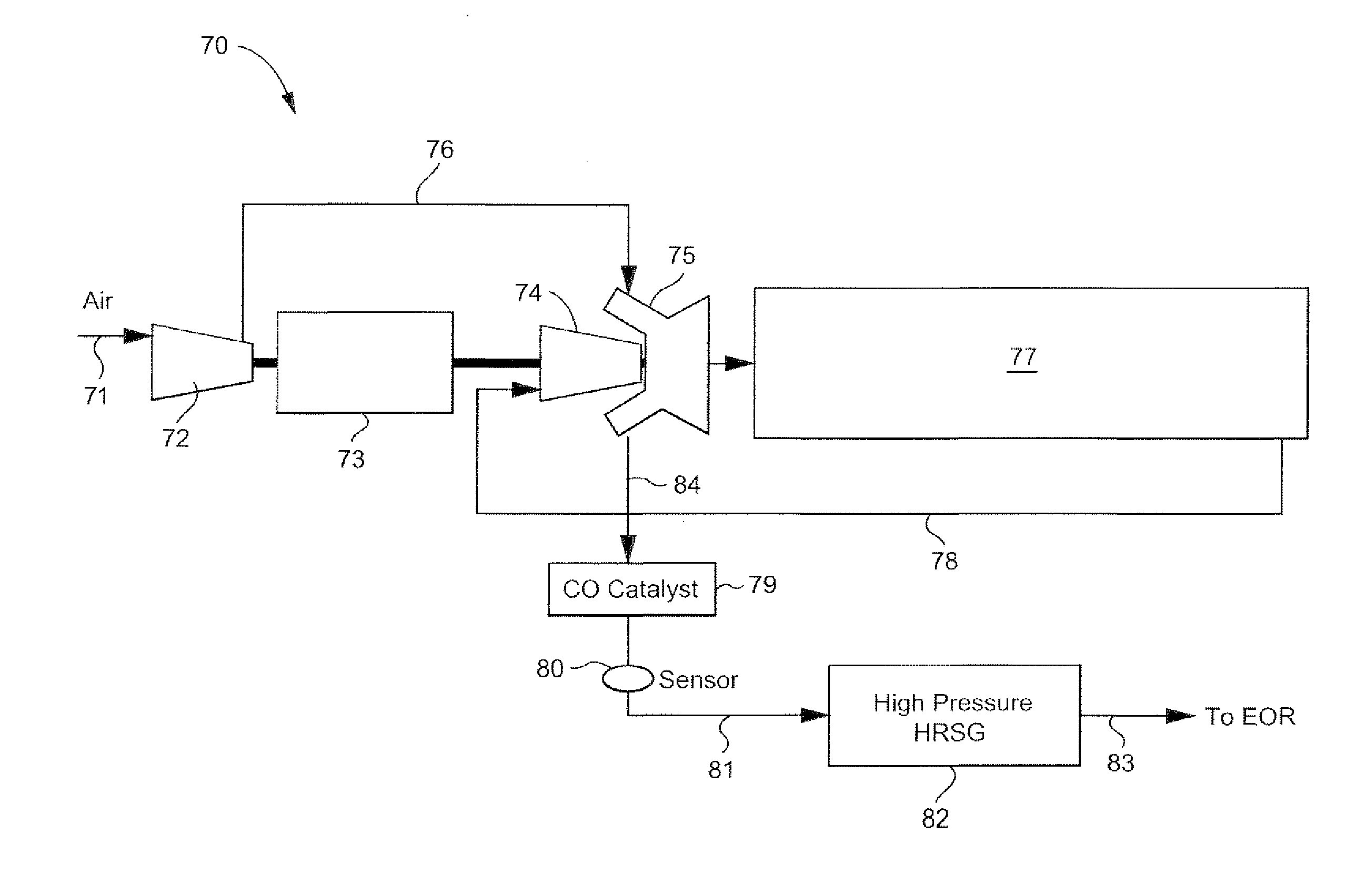
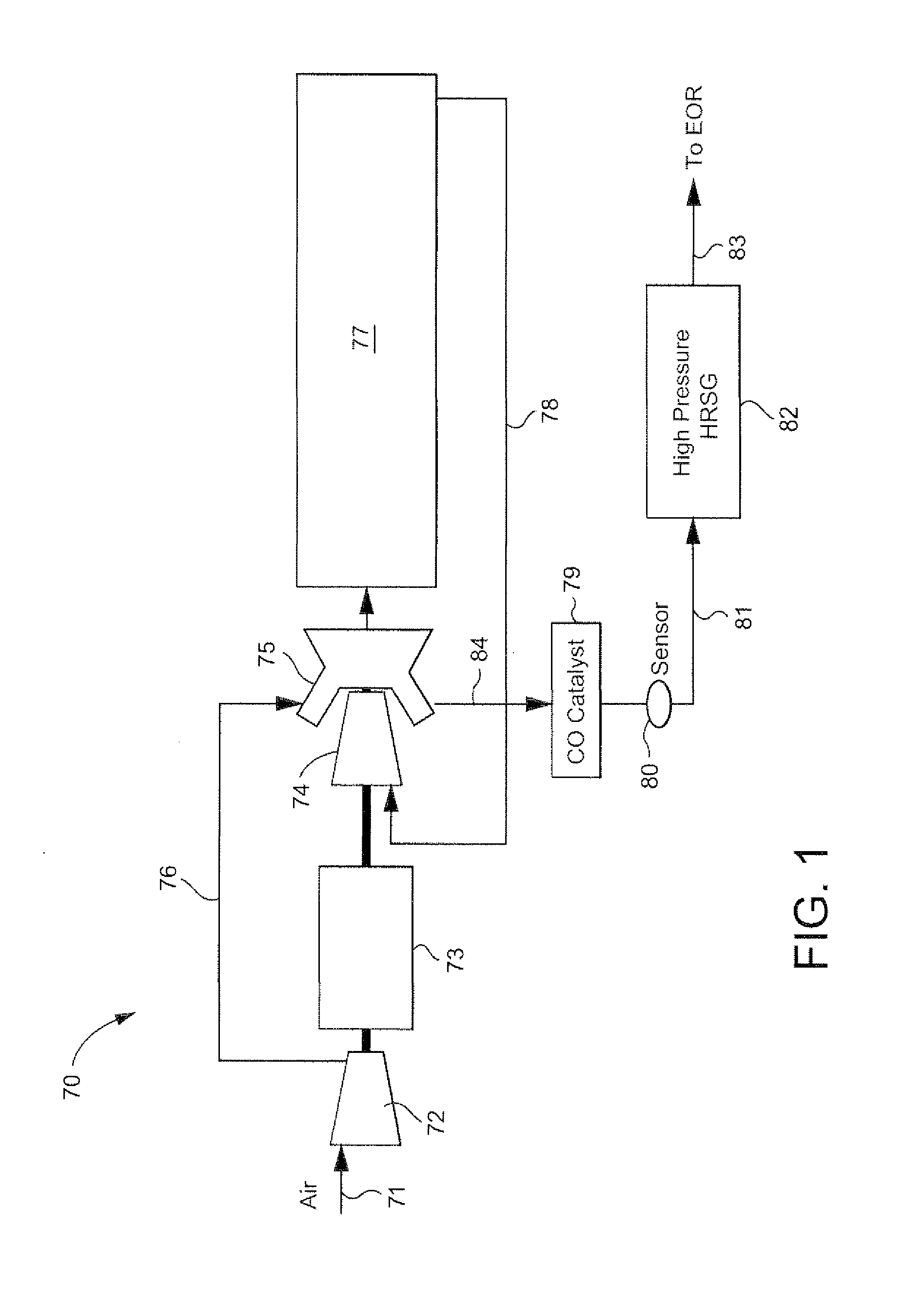
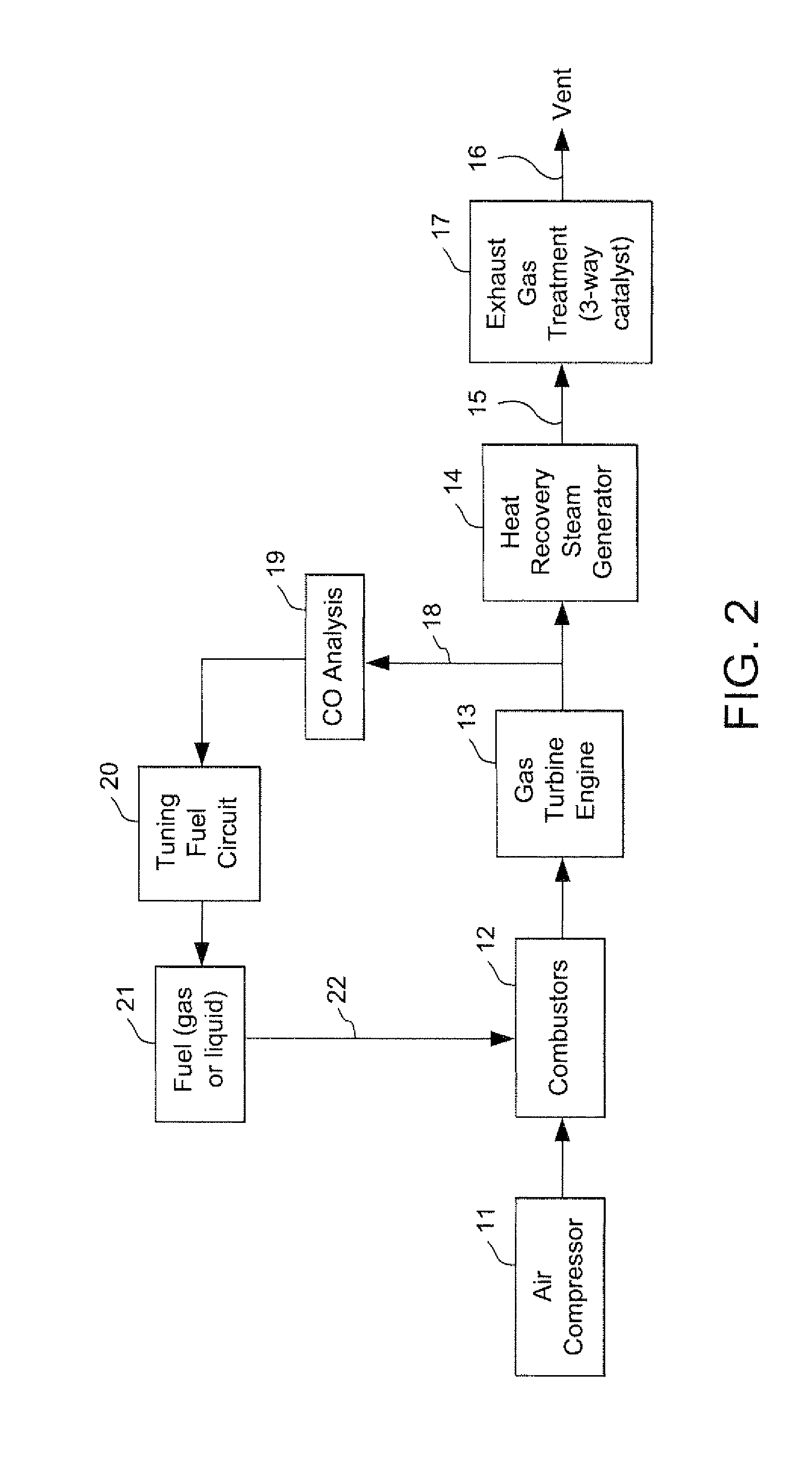
[0018]The stoichiometric exhaust gas recirculation (SEGR) gas turbine engine according to the present invention is intended to provide a zero oxygen content exhaust that can be more effectively treated with a NOx reduction catalyst to provide an exhaust stream free of NOx contaminants. When applied to enhanced oil recovery applications, the invention is ideal for carbon capture and storage processes, and useful in any process where a diluent is required with no oxygen.

[0019]As noted above, in a conventional SEGR gas turbine system, the products of the combustion invariably contain excess oxygen due to the equilibrium chemistry at nominal temperatures of combustion, with some of the CO2 products of combustion disassociating into CO and O2. In addition, perfect mixing of fuel and air cannot be achieved, resulting in some of the oxygen present in the feed not reacting with hydrocarbon fuel. Thus, the resulting exhaust stream, comprised predominantly of N2 and CO2, will still contain sm...


PUM


Abstract

A fuel control system for a gas turbine engine that includes a primary fuel circuit, a fuel tuning circuit, a plurality of combustors connected to the fuel tuning circuit, oxygen and carbon dioxide sensors in the exhaust stream and a feedback control loop operatively connected to the fuel tuning circuit and to the oxygen and carbon monoxide sensors which serve to control the precise amount of fuel and air being fed to each one of the plurality of combustors in the engine. A parallel array of control valves in a tuning fuel circuit connect to corresponding ones of the plurality of combustors in the gas turbine engine. The fuel control system thereby “fine tunes” the amount of fuel and air being fed to each combustor using data regarding the detected oxygen and carbon monoxide concentrations in the exhaust gas as provided through a feedback control loop.

Description

[0001]The present invention relates to gas turbine engine systems and related controls and, more particularly, to a gas turbine engine having a plurality of combustors, each of which can be separately controlled using a feedback control loop to adjust the fuel-to-air ratio based on detected amounts of oxygen and carbon monoxide in the exhaust, while ensuring that unwanted NOx emissions can be removed from the exhaust using a catalyst. The invention provides what is referred to herein as “stoichiometric exhaust gas recirculation (“SEGR”).BACKGROUND OF THE INVENTION[0002]Gas turbine engines typically include a compressor section, a combustor section and at least one turbine that rotates in order to generate electrical power. The compressor discharge feeds directly into the combustor section where hydrocarbon fuel is injected, mixed and burned. The combustion gases are then channeled into and through one or more stages of the turbine which extracts rotational energy from the combustion...

Claims


Application Information

Patent Timeline
IPC IPC(8): F02C7/22F02C7/00
CPCF01K13/02B01D53/9422F02C7/228F02C7/232F02C9/18F05D2260/61F05D2270/082Y02T50/677F02C3/34B01D53/9445B01D53/9495F01N9/00F01N3/0814B01D53/9459F01K23/10Y02T50/60
Inventor DRAPER, SAMUEL DAVID
Owner GENERAL ELECTRIC CO
Why Eureka
Try Eureka