Fluid Displacement Regulated Line Feed System

a technology of regulated line feed and fluid injection, which is applied in the direction of transportation and packaging, process and machine control, instruments, etc., can solve the problems of difficult regulation of the introduction rate and failure to provide an adjustable means for reliably

Inactive Publication Date: 2011-02-24
WALTMAN STEVEN MICHAEL
View PDF15 Cites 1 Cited by
  • Summary
  • Abstract
  • Description
  • Claims
  • Application Information

AI Technical Summary

Problems solved by technology

The rate of introduction is difficult to regulate, since it varies depending on a multitude of conditions; few of which are reliably controllable by this type device.
Though the aforementioned patents may provide means o

Method used


Image

  • Fluid Displacement Regulated Line Feed System
  • Fluid Displacement Regulated Line Feed System
  • Fluid Displacement Regulated Line Feed System

Examples


Embodiment Construction

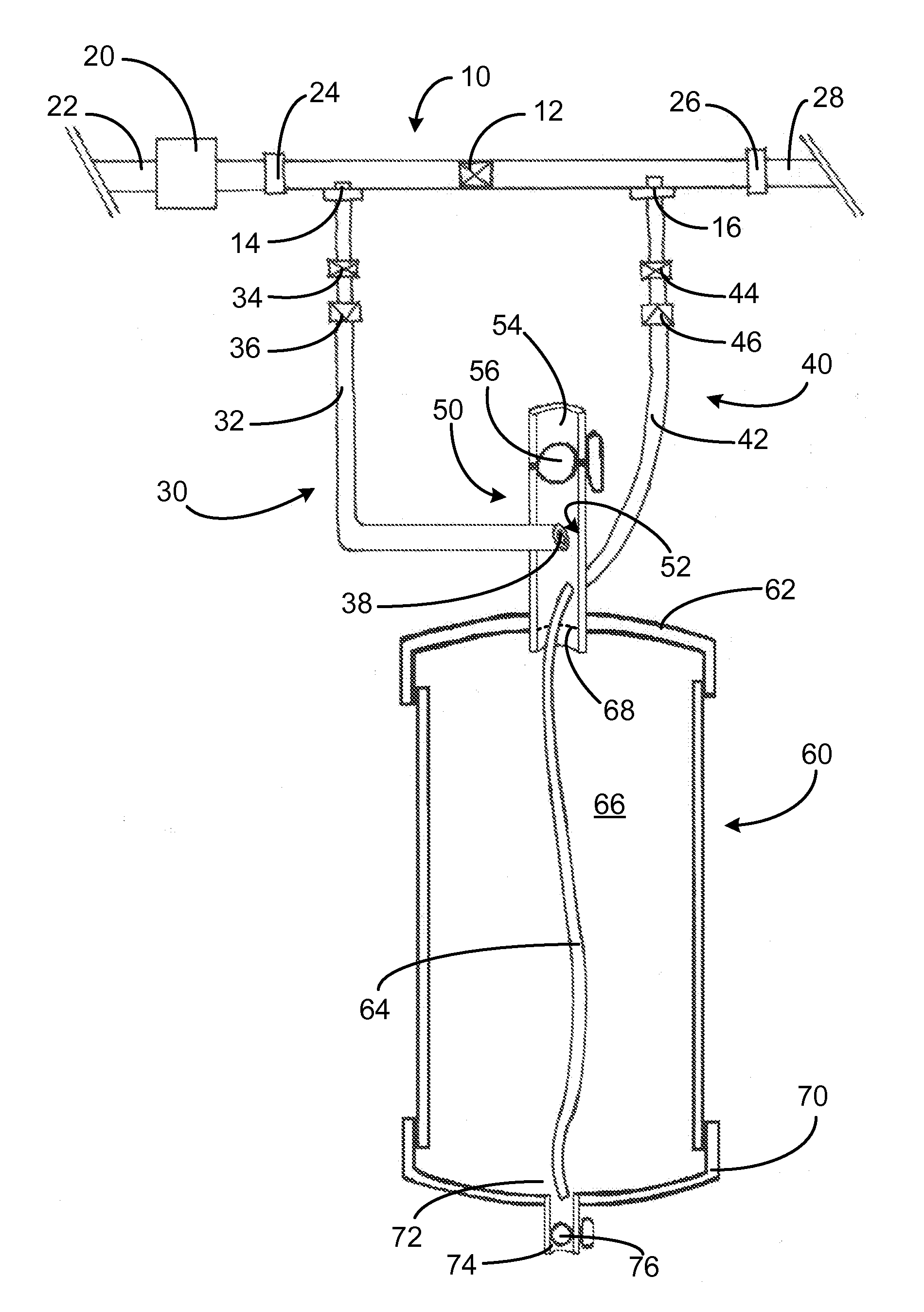
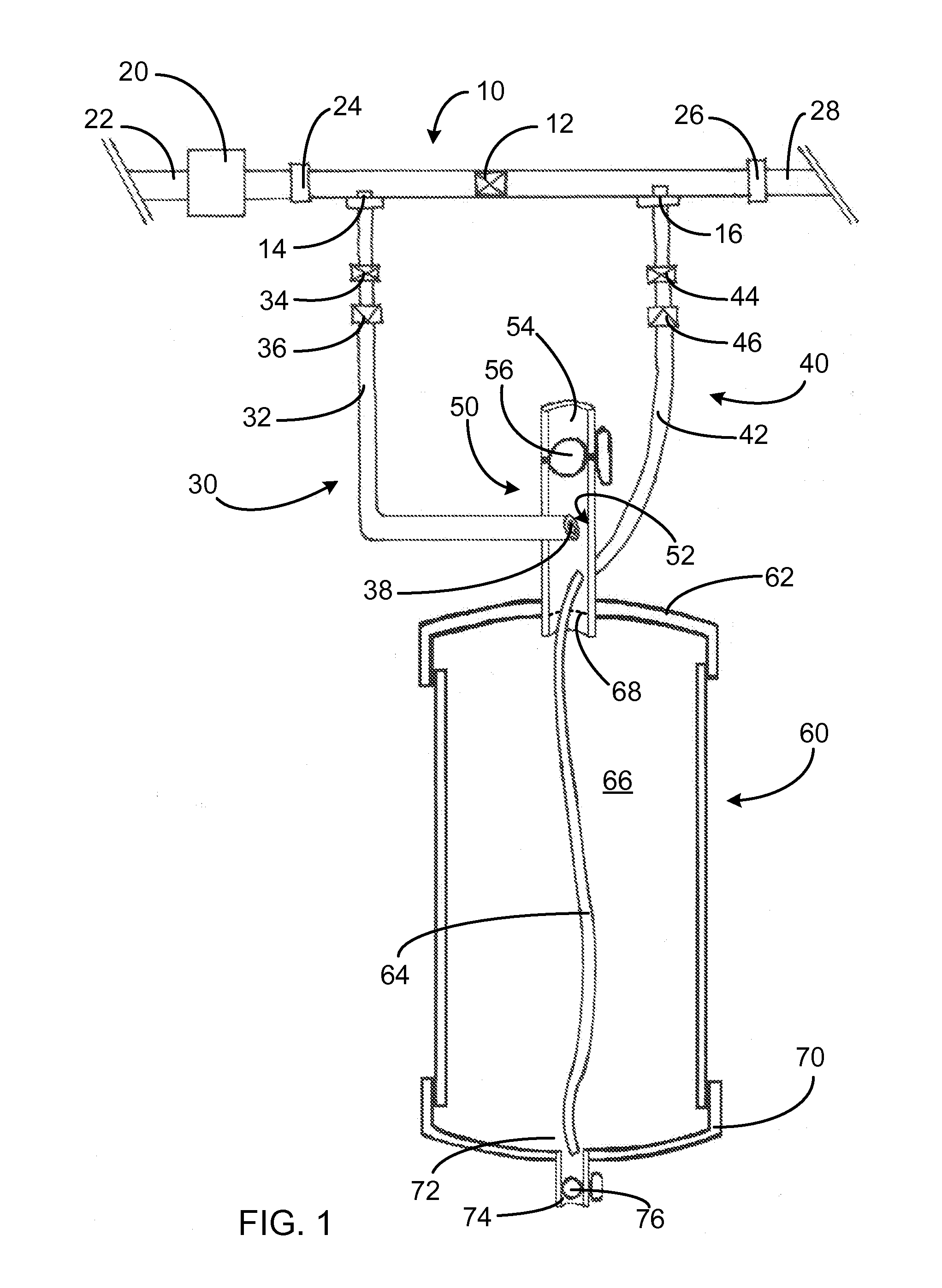
[0019]Now, referring to FIGS. 1, an exemplary liquid additive feed system for a fluid flow line, is shown to include a liquid reservoir 60, a manifold 10, a flow line pressure regulation module 20, a flow controlled inlet line 30, a flow controlled feed line 40, and a diffusion interface 50. The liquid reservoir 60 is oriented with a top and a bottom, so that a liquid additive with a specific gravity of greater than 1 will segregate at the bottom of the reservoir 60 while water introduced to the reservoir 60 will float on top. In a system where the feed line 22 carries an alternative liquid substance, the system would work with a liquid additive having a greater specific gravity than the flow substance.

[0020]The exemplary system is designed for low-pressures and low-feed volumes system in the range of about 15 to 50 pounds per square inch (“PSI”) of pressure and in the range of about 0.1 to 15 gallons per minute (“GPM”) flow rate. (Throughout this disclosure “gallons” will be U.S. g...


PUM


Abstract

A liquid additive feed system for a pressure controlled fluid flow line, which may include a liquid reservoir, a manifold, a flow line pressure regulation module, a flow controlled inlet line, a flow controlled feed line, and a diffusion interface, which dynamically adjustably delivers a metered dosage of liquid additive into a controlled aqueous flow delivery system.

Description

CROSS-REFERENCE TO RELATED APPLICATIONS[0001]This application claims the benefit of provisional patent application No. 61 / 235,353, filed 20 Aug. 2009 by the present inventor.STATEMENT REGARDING FEDERALLY SPONSORED RESEARCH OR DEVELOPMENT[0002]Not ApplicableBACKGROUND OF THE INVENTION[0003]1. Field of the Invention[0004]This invention relates to fluid injection systems for controllably diffusing an additive into a fluid flow. It also relates more specifically to aqueous or water-soluble substance delivery or additive systems that employ a reservoir to contain the additive prior to delivery.[0005]2. Description of the Related Art[0006]A variety of means have been used to blend soluble additives into fluid streams. A widely used device for garden-type applications is a Venturi suction device attached to a jar at the end of a garden hose. Attached to the fluid suction point typically is a tube to the bottom of the jar, which slowly draws the additive from the jar and introduces it into ...

Claims


Application Information

Patent Timeline
IPC IPC(8): G05D11/00
CPCG05D11/006Y10T137/2705Y10T137/87571B01F25/30
Inventor WALTMAN, STEVEN MICHAEL
Owner WALTMAN STEVEN MICHAEL
Why Eureka
Try Eureka