Printed electronics
a technology of printed electronics and printed circuits, applied in resistive material coatings, polyether coatings, inks, etc., can solve the problems of limited substrates, insufficient electrically conductive printed circuits, and insufficient conductive polymers alon
- Summary
- Abstract
- Description
- Claims
- Application Information
AI Technical Summary
Problems solved by technology
Method used
Image
Examples
example 1
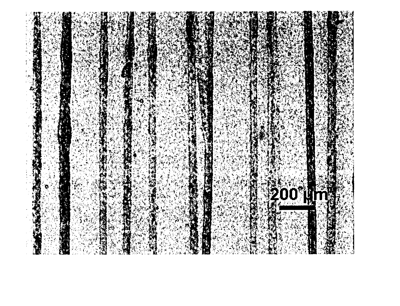
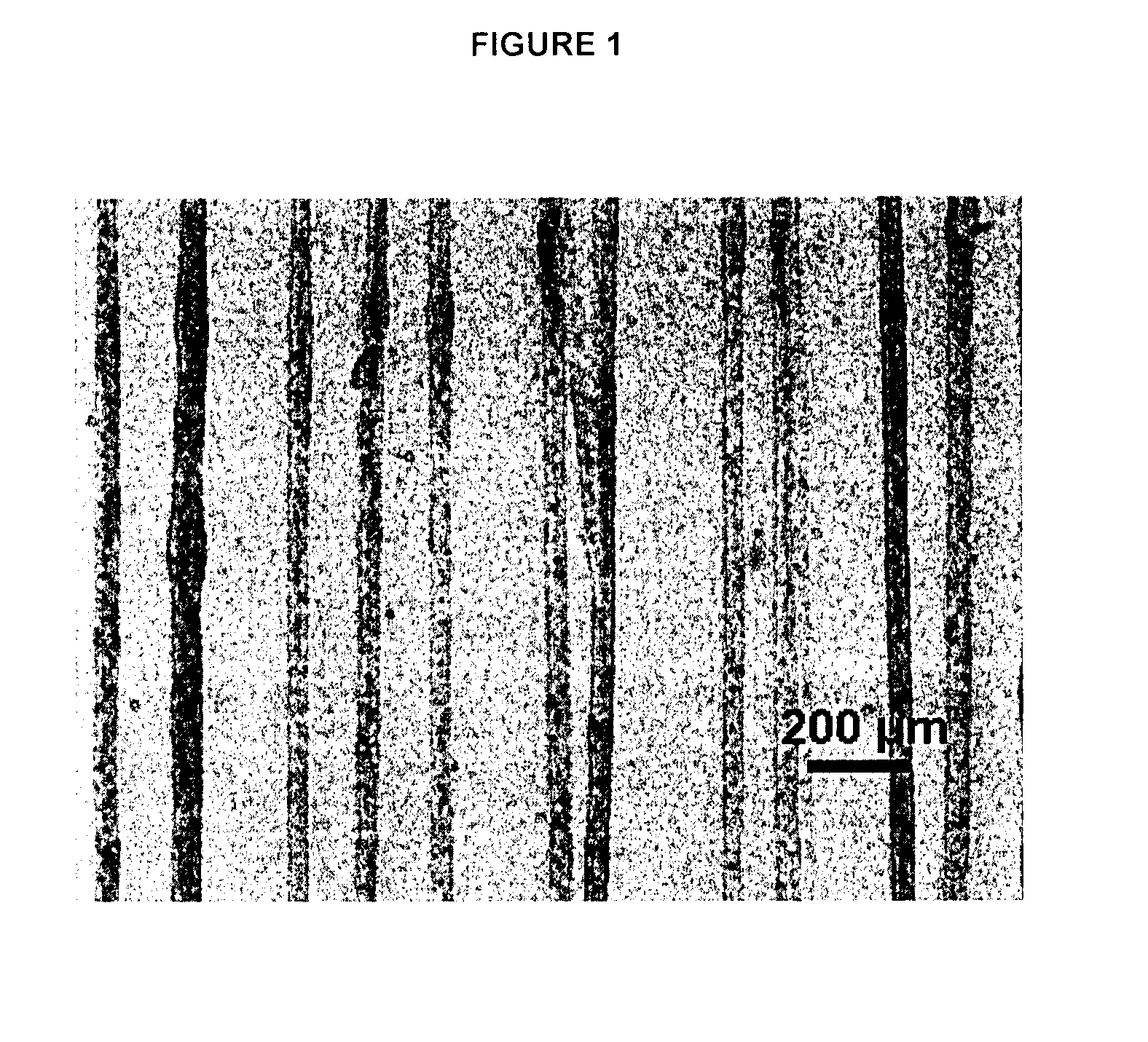
[0056]An ink is prepared as described above using PEO having a molecular weight of 4,000,000. The ink is printed electrohydrodynamically onto a glass substrate using the method disclosed in WO 2007 / 053621. The printing is done at a flow rate of 0.5 mL / hr under a 2200 kV potential difference between electrodes that are 7.2 mm apart. The width of the lines is about 43 μm. FIG. 1 is an optical microscope image of a series of parallel printed lines.
[0057]Copper tapes are attached to the lines perpendicular to the length of the lines. A power supply (Tektronix PS 252G Programmable Power Supply, Tektronix Inc., Beaverton, Oreg.) and a multimeter (Fluke 27 Multimeter, Fluke Corp., Everett, Wash.) are attached in serial with the printed via the copper tapes. A potential difference (5-20 V) is applied and current is monitored through the multimeter. An electrometer (Keithley 6514, Keithley Instruments Inc., Cleveland, Ohio) with two electrodes is used to measure the potential difference acro...
example 2
[0058]An ink is prepared as described above using PEO having a molecular weight of 4,000,000. The ink is printed electrohydrodynamically onto a glass substrate using the method disclosed in WO 2007 / 053621. The printing is done at a flow rate of 0.5 mL / hr under a 2200 kV potential difference between electrodes that are 7.2 mm apart. The width of the lines is about 130 μm.
[0059]The ink is formed into a film as follows: two copper plates (22 mm×22 mm) are wrapped with Teflon tape, leaving 1 mm of copper uncovered at the lower ends. The plates are then firmly attached to the shorter of the side walls of a Teflon® cell (23 mm×46 mm inner base area, 32 mm height) with screws. The mixture is poured into the Teflon® cell and kept at 50° C. on a hot plate until all of the solvent is evaporated to form films that are attached to the copper plates.
[0060]Copper tapes are attached parallel to each other on two ends of the film such that they cover the entire width of the film. The electrical con...
example 3
[0063]An ink is prepared as described above using PEO having a molecular weight of 4,000,000. The ink is printed electrohydrodynamically onto a glass substrate using the method disclosed in WO 2007 / 053621. The printing is done at a flow rate of 0.5 mL / hr under a 2200 kV potential difference between electrodes that are 7.2 mm apart. The width of the lines is about 140 μm and the thickness is about 300 nm. The printed line has an electrical conductivity of about 19.6 S / m.
General Details for Examples 4-14
Preparation of Test Samples
[0064]The inks in the form of liquid dispersions are printed onto a substrate using a doctor blade and then dried in air in an oven at 125° C. to form a film. Testing is done on the printed films.
Electrical Conductivity
[0065]The point-to-point resistivity (in ohms) of the films is measured using a standard multimeter across contact points consisting of two spots of silver paste having a diameter of about 0.3 mm that are applied to the surface of the film abou...
PUM
 Abstract
Description
Claims
Application Information
 - R&D
- Intellectual Property
- Life Sciences
- Materials
- Tech Scout
- Unparalleled Data Quality
- Higher Quality Content
- 60% Fewer Hallucinations
Browse by: Latest US Patents, China's latest patents, Technical Efficacy Thesaurus, Application Domain, Technology Topic, Popular Technical Reports.
© 2025 PatSnap. All rights reserved.Legal|Privacy policy|Modern Slavery Act Transparency Statement|Sitemap|About US| Contact US: help@patsnap.com


