Unlock instant, AI-driven research and patent intelligence for your innovation.

Signal processing device, imaging device, and signal processing method

a signal processing and imaging device technology, applied in the field of signal processing devices, imaging devices, and signal processing methods, can solve the problems of inability to accurately determine the correlation direction and disadvantageous improvement in color interpolation accuracy, and achieve the effect of accurate and reliable g color difference signals

Active Publication Date: 2011-02-24
SONY CORP
View PDF4 Cites 7 Cited by
  • Summary
  • Abstract
  • Description
  • Claims
  • Application Information

AI Technical Summary

Benefits of technology

[0014]It is desirable to provide a signal processing device, an imaging device, and a signal processing method in which color interpolation can be accurately performed without increasing the data amount and calculation amount even in an edge part and the like of an image.
[0020]According to “constant hue hypothesis” mentioned above, even when accuracy of a produced G color difference signal is insufficient, a more reliable G color difference signal can be obtained by collecting and averaging a plurality of G color difference signals. Thus, the above structure enables color interpolation to be accurately performed even in an edge part and the like in which accuracy of a G color difference signal is easily degraded.

Problems solved by technology

Therefore, the correlation direction is not correctly determined when a difference between a pixel value obtained by the color interpolation and a pixel value of an original image is extensive.
That is, accuracy in the color interpolation is not improved disadvantageously in such case.

Method used


Image

  • Signal processing device, imaging device, and signal processing method
  • Signal processing device, imaging device, and signal processing method
  • Signal processing device, imaging device, and signal processing method

Examples


Embodiment Construction

[0034]A signal processing device, an imaging device, and a video signal processing method according to an embodiment of the present invention will now be described with reference to the accompanying drawings in the following order.[0035]1. Structural Example of Imaging Device[0036]2. Structural Example of Color Interpolation Processing Unit[0037]3. Structural Example of G Color Difference Re-constituting Unit[0038]4. Operation Example of G Color Difference Re-constituting Unit

1. Structural Example of Imaging Device

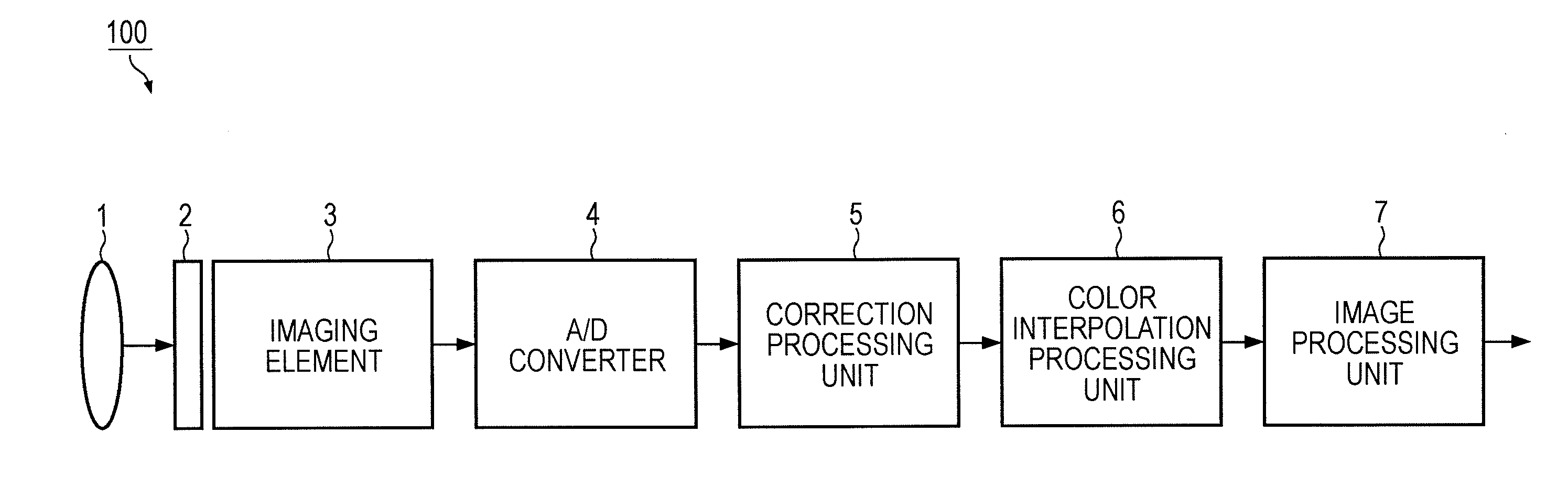
[0039]In the embodiment of the present invention, a case where a signal processing device according to the embodiment of the present invention is applied to an imaging device such as a camera will be described as an example. FIG. 1 illustrates an example of the structure inside a camera block of an imaging device 100 according to the embodiment. The camera block shown in FIG. 1 includes a lens 1, a color filter 2, an imaging element 3, an analog-digital converting unit 4 (...


PUM


Abstract

A signal processing device includes a preprocessing unit interpolating a G color component to positions of a pixel of interest and a pixel having the same color component as the pixel of interest so as to produce a first G interpolation signal; a proximity G pixel G color difference and R / B pixel producing unit producing a first R-G / B-G color difference signal on the positions of the pixel of interest and the pixel having the same color component, producing a second R-G / B-G color difference signal on a position of a proximity G pixel, and interpolating the R / B color component to the position of the proximity G pixel; a G color difference re-constitution processing unit re-constituting a third R-G / B-G color difference signal on the position of the pixel of interest; and a G color difference interpolation processing unit interpolating an R-G / B-G color difference signal to a position of a predetermined pixel.

Description

BACKGROUND OF THE INVENTION[0001]1. Field of the Invention[0002]The present invention relates to a signal processing device, an imaging device, and a signal processing method. In particular, the present invention relates to a technique of interpolating color information to each pixel signal obtained through a color filter array, for example.[0003]2. Description of the Related Art[0004]In a single-plate type imaging device, a color filter array is used so as to separate object light obtained through a lens into three primary colors of R (red), G (green), and B (blue). A Bayer array is commonly used as the color filter array. An example of the Bayer array is illustrated in FIG. 13. In the Bayer array, G pixels to which a luminance signal contributes at a high rate are arranged checkerwise and R pixels and B pixels are respectively arranged checkerwise in the rest part of the array.[0005]Since each pixel can obtain data of only one color among R, G, and B, data of other colors, which a...

Claims


Application Information

Patent Timeline
IPC IPC(8): H04N5/335
CPCG06T1/00H04N2209/046H04N9/045H04N23/843H04N25/134
Inventor YAMAGUCHI, YUYAKAWASHIMA, MANABU
Owner SONY CORP
Features
  • R&D
  • Intellectual Property
  • Life Sciences
  • Materials
  • Tech Scout
  • Unparalleled Data Quality
  • Higher Quality Content
  • 60% Fewer Hallucinations
Learn More