
Video processing apparatus and method for controlling the same

Inactive Publication Date: 2011-02-24
CANON KK
View PDF12 Cites 45 Cited by
  • Summary
  • Abstract
  • Description
  • Claims
  • Application Information

AI Technical Summary

Benefits of technology

[0012]According to an aspect of the present invention, there is provided a video processing apparatus which determines whether a video signal of a predetermined resolution is a pseudo-resolution video signal generated from a video signal of resolution lower than the predetermined resolution. The video processing apparatus includes a first generation unit configured to generate a first frequency histogram relating to a video signal of a first resolution among a plurality of video signals which are identical in contents and different from one another in resolution, a second generation unit configured to generate a second frequency histogram relating to a video signal of a secon

Problems solved by technology

More specifically, by using the pseudo-resolution video disadvantageous in image quality as compared with the original resolution video, the video is down-converted again to lower resolution.
In consequence, image quality deterioration occurs in the technique discussed in the above reference.
However, in the above described pseudo-resolution video determination method of the conventional technology, certain videos are erroneously detected.
For example, in the case of a video such as a cartoon which includes many flat portions and smooth edges, a spatial frequency is originally low, and hence it is difficult to determine whether a video signal is a pseudo-resolution video signal.

Method used


Image

  • Video processing apparatus and method for controlling the same
  • Video processing apparatus and method for controlling the same
  • Video processing apparatus and method for controlling the same

Examples


Embodiment Construction

[0021]Various exemplary embodiments, features, and aspects of the invention will be described in detail below with reference to the drawings.

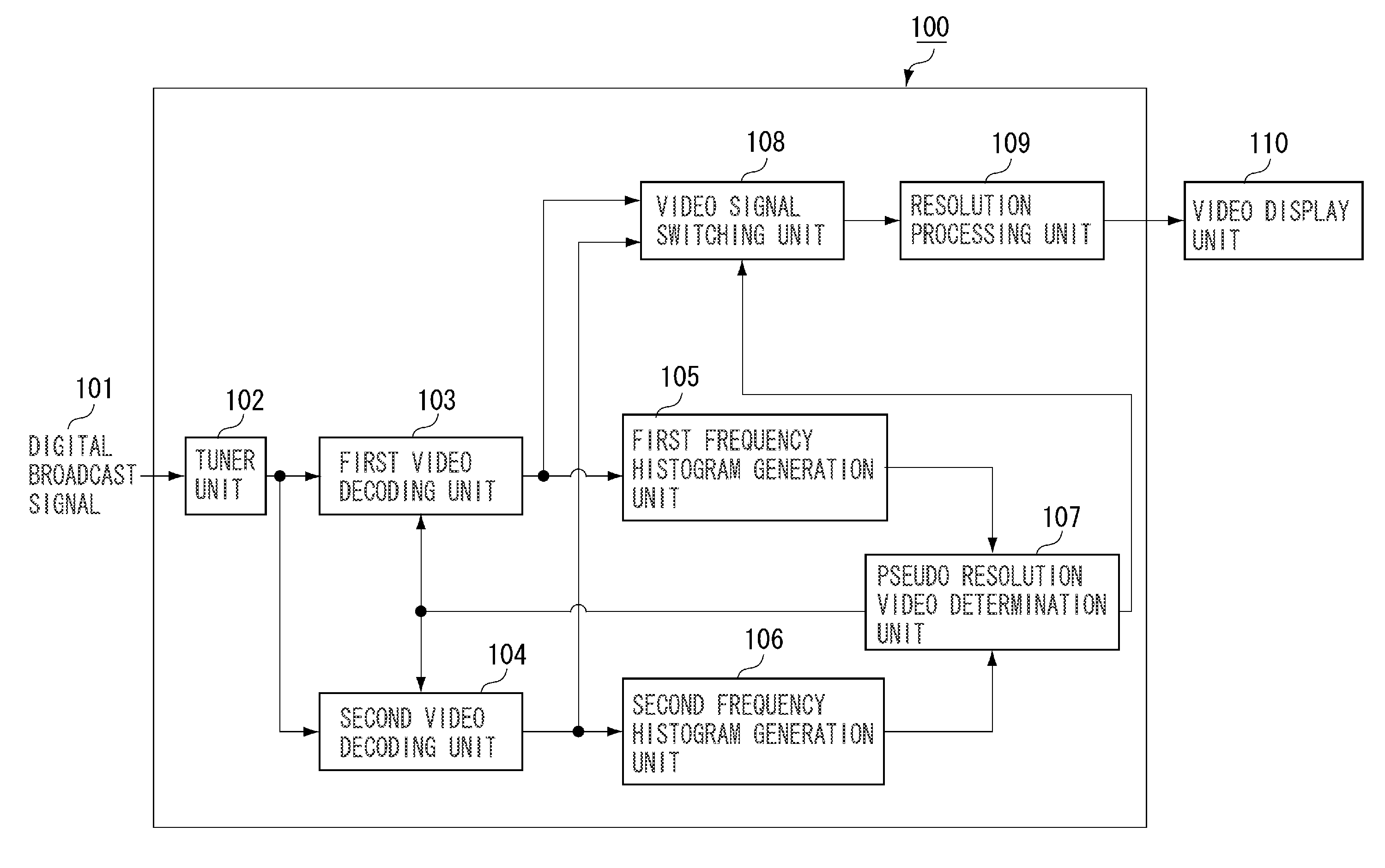
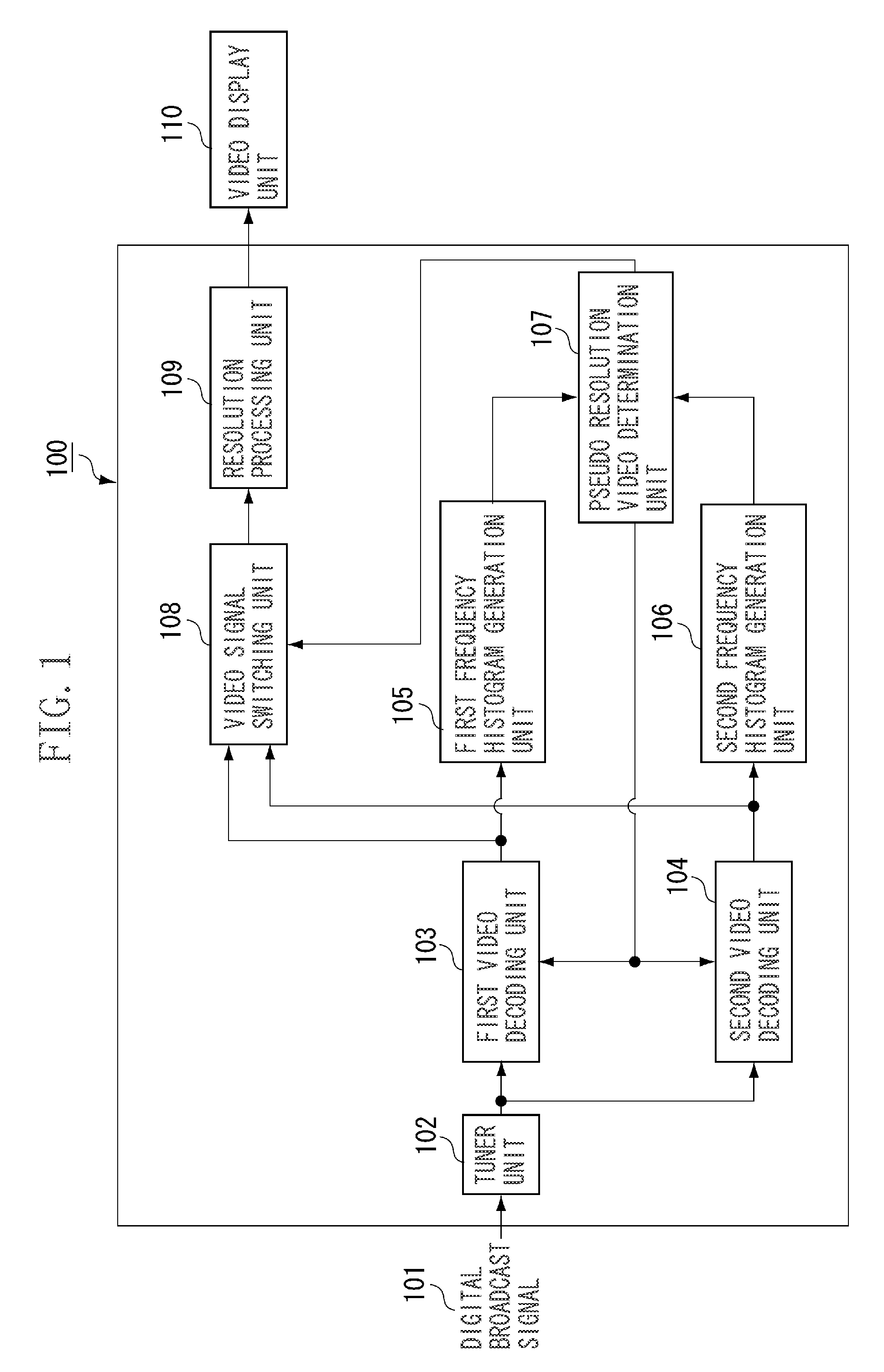
[0022]FIG. 1 is a block diagram illustrating a configuration of a video processing apparatus 100 to which the present invention can be applied. Though not illustrated, a central processing unit (CPU) responsible for overall control of blocks of the video processing apparatus is connected to each block via a bus (not illustrated).

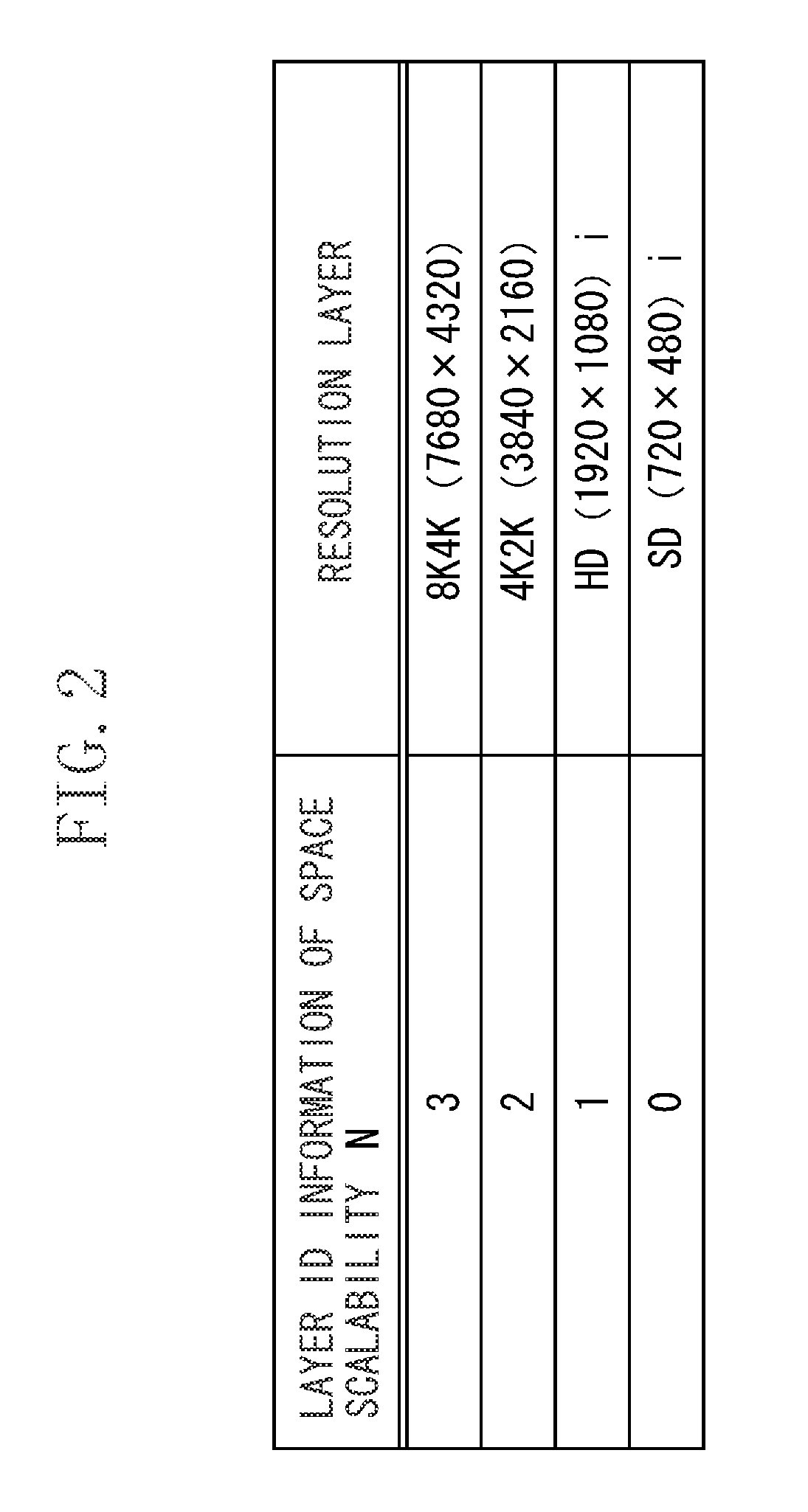
[0023]A digital broadcast signal 101 is input to a tuner unit 102. A Moving Picture Experts Group-2 Transport Stream (MPEG-2 TS) signal of an arbitrary channel is extracted from the input digital broadcast signal 101. The MPEG-2 TS signal in which a video signal coded by the H.264 / SVC and an audio signal coded by Advanced Audio Coding (AAC) are multiplexed is separated at the tuner unit 102. It is defined that spatial scalability (selectable resolution) can be set up to eight layers in the video coded by the H.264 / SVC.

[...


PUM


Abstract

A video processing apparatus determines whether a video signal of a predetermined resolution is a pseudo-resolution video signal generated from a video signal of resolution lower than the predetermined resolution. The video processing apparatus generates a first frequency histogram relating to a video signal of a first resolution among a plurality of video signals which are identical in contents and different from one another in resolution and a second frequency histogram relating to a video signal of a second resolution which is lower than the first resolution, compares the first frequency histogram with the second frequency histogram, compares a similarity between the first frequency histogram and the second frequency histogram with a predetermined threshold value, and determines, if the similarity is equal to or less than the predetermined threshold value, that the video signal of the first resolution is a pseudo-resolution video signal.

Description

BACKGROUND OF THE INVENTION[0001]1. Field of the Invention[0002]The present invention relates to a video processing apparatus which can generate displayable video data from a video signal which has predetermined resolution among video signals which are identical in contents but different from one another in resolution, and a method for controlling the video processing apparatus.[0003]2. Description of the Related Art[0004]Conventional analog broadcasting has handled mainly videos of Standard Definition (SD) resolution. In current digital broadcasting, however, videos are broadcast with High Definition (HD) resolution based on a high-compression video coding technique in many cases. Thus, in the case of broadcasting contents generated using conventional equipment of SD resolution or past contents of SD resolution, interpolation processing is performed to increase the number of pixels, and a video having only apparent resolution converted into HD resolution may have been distributed. ...

Claims


Application Information

Patent Timeline
IPC IPC(8): H04N9/74
CPCH04N7/0125H04N17/004H04N7/015
Inventor KURITA, MASANAOMIZUTOME, ATSUSHI
Owner CANON KK
Learn More