Method for Passive Seismic Emission Tomography Including Polarization Correction for Source Mechanism

Inactive Publication Date: 2011-02-24
MICROSEISMIC
View PDF3 Cites 35 Cited by
  • Summary
  • Abstract
  • Description
  • Claims
  • Application Information

AI Technical Summary

Problems solved by technology

A limitation of the method disclosed in the '929 publication relates to the spatial orientation and radiation pattern of the event giving rise to seismic signals detected at the Earth's surface.
Further, there are typically large numbers of seismic sensors disposed at the surface for which synthesis would have to be performed.

Method used


Image

  • Method for Passive Seismic Emission Tomography Including Polarization Correction for Source Mechanism
  • Method for Passive Seismic Emission Tomography Including Polarization Correction for Source Mechanism
  • Method for Passive Seismic Emission Tomography Including Polarization Correction for Source Mechanism

Examples


Embodiment Construction

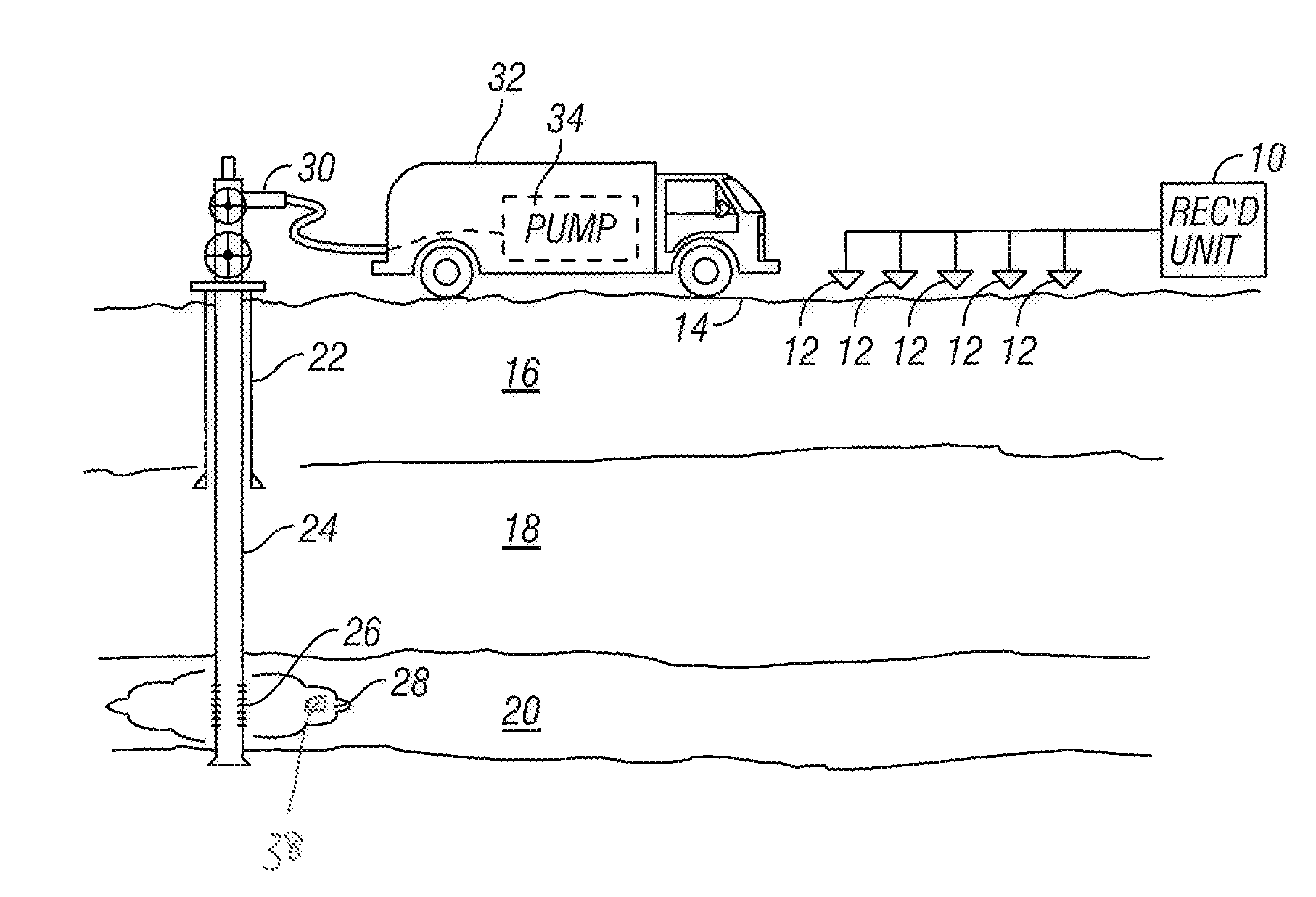
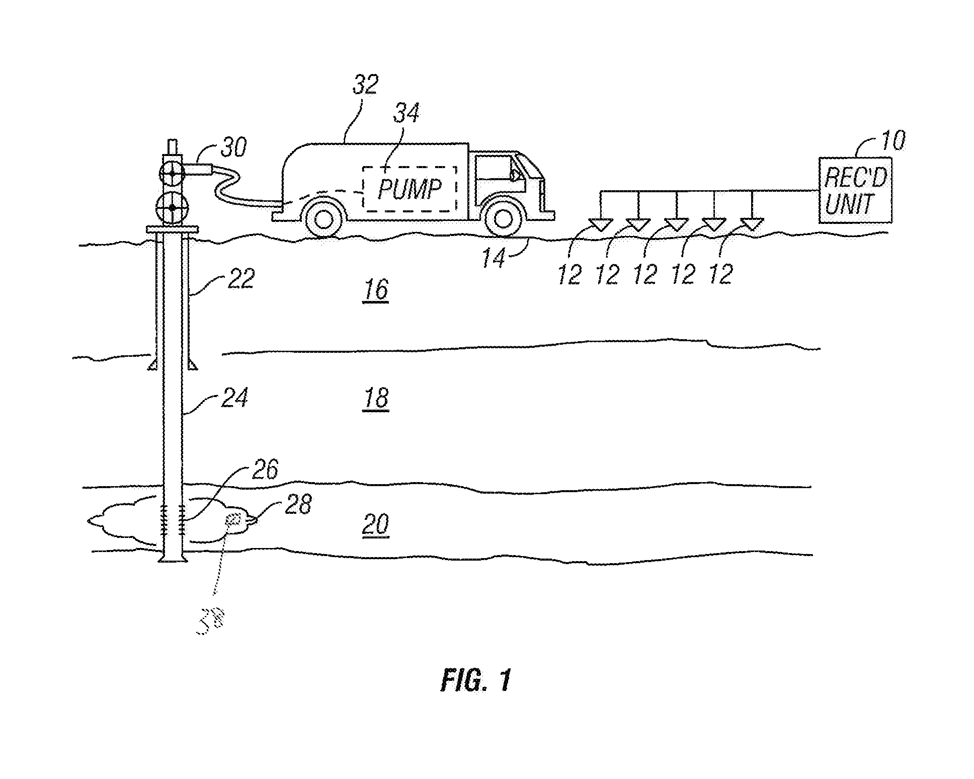
[0019]FIG. 1 shows a typical arrangement of seismic sensors as they would be used in one application of a method according to the invention. The embodiment illustrated in FIG. 1 is associated with an application for passive seismic emission tomography known as “fracture monitoring.” It should be clearly understood that the application illustrated in FIG. 1 is only one possible application of a method according to the invention.

[0020]In FIG. 1, each of a plurality of seismic sensors, shown generally at 12, is deployed at a selected position proximate the Earth's surface 14. In marine applications, the seismic sensors would typically be deployed on the water bottom in a device known as an “ocean bottom cable.” The seismic sensors 12 in the present embodiment may be geophones, but may also be accelerometers or any other sensing device known in the art that is responsive to velocity, acceleration or motion of the particles of the Earth proximate the sensor. The seismic sensors 12 genera...


PUM


Abstract

A method for seismic event mapping includes selecting a plurality of subvolumes representing possible locations of origin of a seismic event in the Earth's subsurface. For each subvolume a plurality of possible directions of motion of subsurface formations is selected. For each subvolume and each possible direction of motion, polarity correction is applied to seismic signals recorded at a plurality of positions proximate a volume of the Earth's subsurface to be evaluated. The polarity correction is based on the direction of motion and the position of each seismic sensor with respect to the subvolume. The recorded, polarity corrected seismic signal recordings are time aligned. The time aligned recordings are summed. A most likely direction of motion and subvolume position are determined based on a selected attribute of the summed, time aligned seismic signals.

Description

CROSS-REFERENCE TO RELATED APPLICATIONS [0001]Not applicable.STATEMENT REGARDING FEDERALLY SPONSORED RESEARCH OR DEVELOPMENT[0002]Not applicable.BACKGROUND OF THE INVENTION [0003]1. Field of the Invention[0004]The invention relates generally to the field of seismic data acquisition and processing to image subsurface Earth formation structures. More specifically, the invention relates to methods for acquiring and processing passive seismic data, that is, seismic data acquired without the use of a controllable source.[0005]2. Background Art[0006]Passive seismic emission tomography is a process in which an array of seismic sensors is deployed in a selected pattern on the Earth's surface (or on the water bottom in marine surveys) and seismic energy is detected at the sensors that emanates from various seismic events occurring within the Earth's subsurface. Processing the signals detected by the sensors is used to determine, among other things, the position in the Earth's subsurface at w...

Claims


Application Information

Patent Timeline
Patent Type & Authority Applications(United States)
IPC IPC(8): G01V1/28
CPCG01V1/288G01V1/40G01V1/42G01V2210/65G01V2210/144G01V2210/55G01V2210/1234
Inventor THORNTON, MICHAEL P.EISNER, LEO
Owner MICROSEISMIC
Why Eureka
Try Eureka