Arrangement and method for the intra-operative determination of the position of a joint replacement implant

a joint replacement and position technology, applied in the field of arrangement for the intraoperative determination of the position of a joint replacement implant, can solve the problems of inability to directly transform into one another, additional risk of infection, and inability to operate quickly and easily, so as to improve the surgical effect, and reduce the risk of error

Inactive Publication Date: 2005-07-07
SMITH & NEPHEW ORTHOPAEDICS
View PDF42 Cites 175 Cited by
  • Summary
  • Abstract
  • Description
  • Claims
  • Application Information

AI Technical Summary

Benefits of technology

[0015] Starting from the prior art, the invention is based on the problem of providing an arrangement of that kind which is quickly and easily operated by the operating surgeon with a very low risk of error and which enables significantly improved surgical results to be achieved.

Problems solved by technology

Nevertheless, the long-term success of joint replacement implantations is even today still closely associated with the experience of the operating surgeon, and this must to a considerable extent be attributed to the difficulties, which are not to be underestimated, of appropriate intra-operative utilization of visual images for achieving optimum alignment of the components of the joint implant in relation to the effective centers of rotation and load axes of the individual patient.
Since, however, any surgical intervention constitutes a risk to the patient and needle pricks cause bleeding and an additional risk of infection in the region of the bones, it is undesirable to perform an additional surgical intervention in the hip region or to insert needles along the femur in order to establish the location of the center of rotation.
Furthermore, the femur needs to be firmly fixed on the measurement table of a registration device, because otherwise the hip socket may become displaced during the probing procedure, with the possibility that, once the registration of the femur coordinates is complete, the cutting jig will be incorrectly positioned.
Since the two sets of data—intra-operatively sensed points and 3D model—do not contain known identical point information, they cannot be transformed into one another directly.
A problem is the generation of the surface for the calculation of the normal to the surface through the individual point.
In conventional triangular meshing, jumps and edges cannot be avoided.
This has the result that a small shift of the surface would result in extreme changes in the normal direction.
Unfortunately, however, in insufficiently defined regions (e.g. margin) this results in excessive vibrations which are then very far from the true surface.
The spline approach fails especially in the case of smooth surfaces, where, however, triangular meshing gives good results.

Method used


Image

  • Arrangement and method for the intra-operative determination of the position of a joint replacement implant
  • Arrangement and method for the intra-operative determination of the position of a joint replacement implant
  • Arrangement and method for the intra-operative determination of the position of a joint replacement implant

Examples


Embodiment Construction

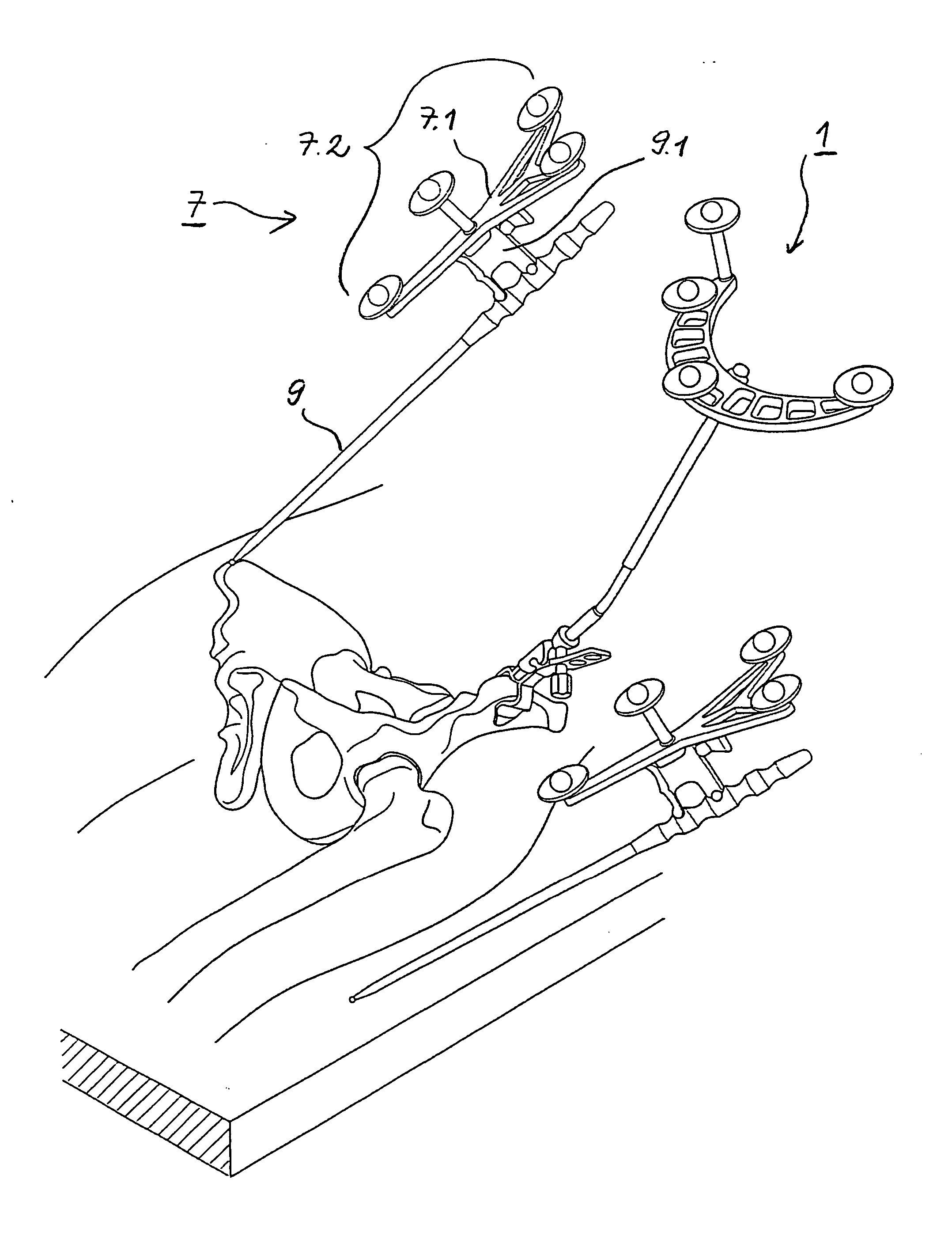
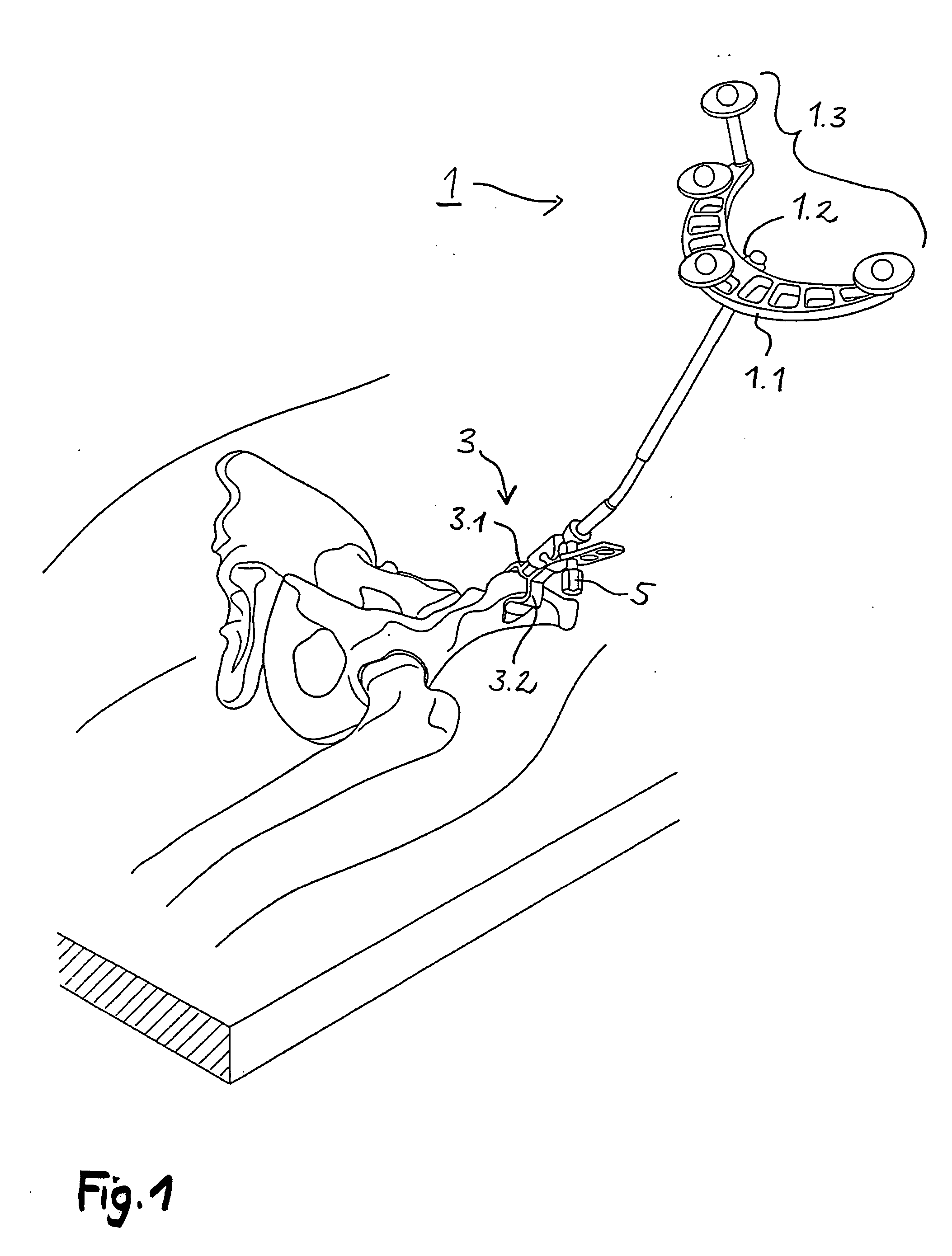
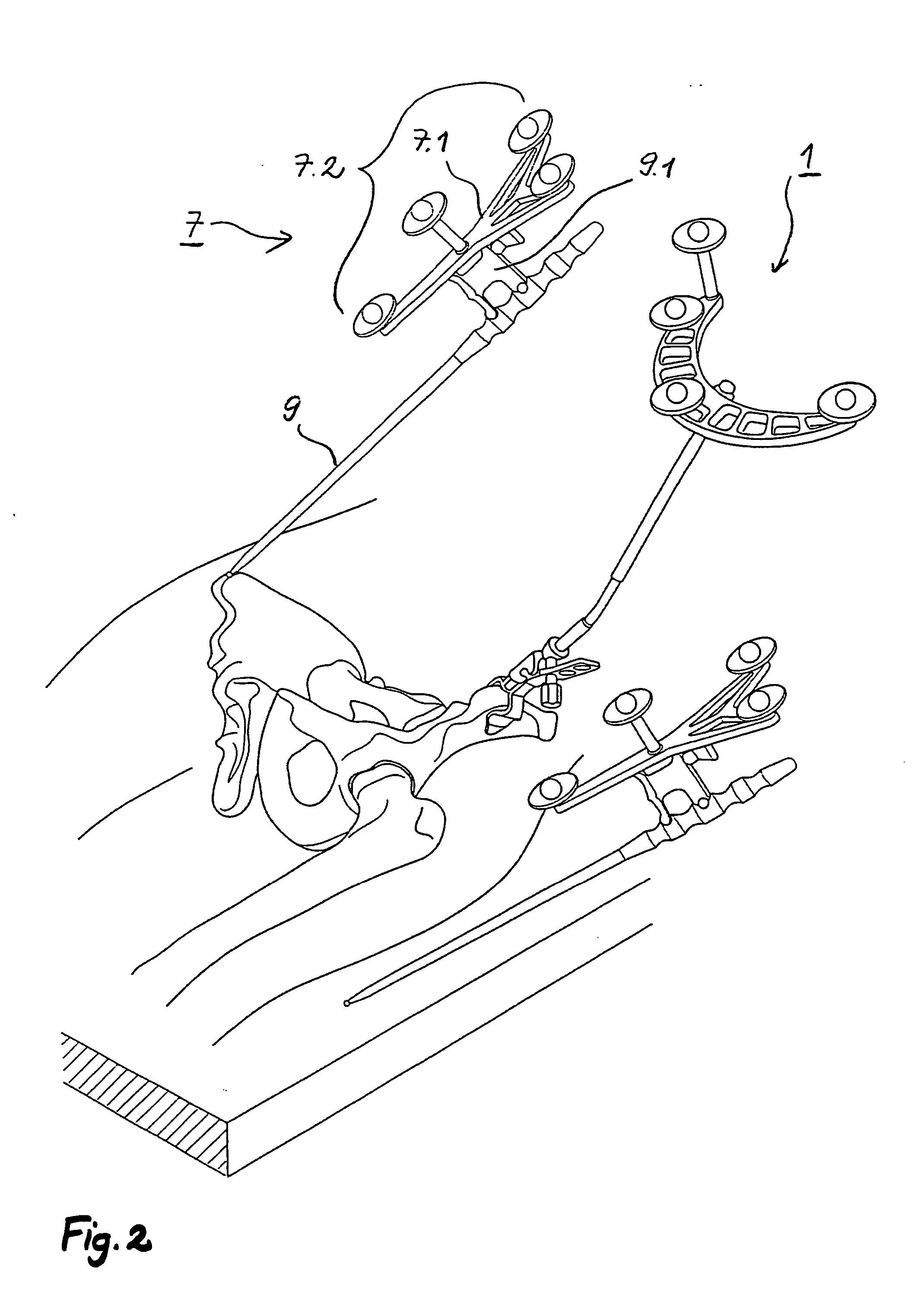
[0076] The following description is given primarily with reference to a procedure for determining the relevant geometric parameters and for implanting a hip socket, but reference is additionally made also to the determination (relatively independent thereof) of the relevant geometric parameters and the implantation of a stem component as the second component of an artificial hip joint.

[0077] The operating surgeon, when planning a hip joint implantation, needs to determine the following values for the socket:

[0078] 1. Size of the Artificial Socket

[0079] 2. Angle of Inclination and Antetorsion Angle

[0080] The two angles of alignment of the socket axis relative to the body planes are here selected on an X-ray image by the operating surgeon in accordance with medical standpoints. These angles can likewise be modified by the operating surgeon intra-operatively.

[0081] 3. Angle in the Sagittal Body Plane Between Vertical Axis and the Direction from the Iliac Crest to the Symphisis.

[0...


PUM


Abstract

Arrangement for the intra-operative determination of the spatial position and angular position of a joint replacement implant, especially a hip socket or shoulder socket or an associated stem implant, or a vertebral replacement implant, especially a lumbar or cervical vertebral implant, using a computer tomography method, having: a computer tomography modeling device for generating and storing a three-dimensional image of a joint region or vertebral region to be provided with the joint replacement implant, an optical coordinate-measuring arrangement for providing real position coordinates of defined real or virtual points of the joint region or vertebral region and/or position reference vectors between such points within the joint region or vertebral region or from those points to joint-function-relevant points on an extremity outside the joint region or vertebral region, the coordinate-measuring arrangement comprising a stereocamera or stereocamera arrangement for the spatial recording of transducer signals, at least one multipoint transducer, which comprises a group of measurement points rigidly connected to one another, and an evaluation unit for evaluating sets of measurement point coordinates supplied by the multipoint transducer(s) and recorded by the stereocamera, and a matching-processing unit for real position matching of the image to the actual current spatial position of the joint region or vertebral region with reference to the real position coordinates of the defined points, the matching-processing unit being configured for calculating transformation parameters with minimalization of the normal spacings.

Description

RELATED APPLICATIONS [0001] This is a Continuation of PCT application PCT / EP03 / 04469, which was filed Apr. 29, 2003 and published in German on Nov. 27, 2003 as WO 03 / 096870, and which is incorporated herein by reference. The above PCT application claims priority to German patent application Serial Nos. 102 22 415.3, filed May 21, 2002 and 103 06 793.0, filed Feb. 18, 2003.BACKGROUND [0002] 1. Field of the Invention [0003] The invention relates to an arrangement for the intra-operative determination of the position of a joint replacement implant, especially a hip socket or shoulder socket or an associated stem implant or a vertebral replacement implant, using a computer tomography method. It relates also to a corresponding method. [0004] 2. Description of the Related Art [0005] Surgical interventions for the replacement of joints or joint components in human beings have been known for a long time and form part of everyday clinical procedure in industrialized countries. For decades, i...

Claims


Application Information

Patent Timeline
Patent Type & Authority Applications(United States)
IPC IPC(8): A61B5/103A61B17/00A61B17/15A61B17/17A61B17/32A61B17/56A61B19/00A61F2/46
CPCA61B5/103A61B5/6884A61B5/4528A61B17/15A61B17/1746A61B19/50A61B19/52A61B19/5244A61B19/56A61B2017/00464A61B2019/505A61B2019/5255A61B2019/5268A61B2019/5272A61B2019/5483A61F2/4609A61F2/4611A61F2/4612A61B5/6878A61B5/1071A61B2090/3983A61B90/36A61B2034/2055A61B2034/2068A61B2034/2072A61B34/20A61B34/25A61B34/10A61B2034/105
Inventor STIFTER, JANBROERS, HOLGER
Owner SMITH & NEPHEW ORTHOPAEDICS
Why Eureka
Try Eureka