[0029]Referring now to the drawings, an embodiment of an extraction preventing device for a connector in accordance with the present invention will be described below.
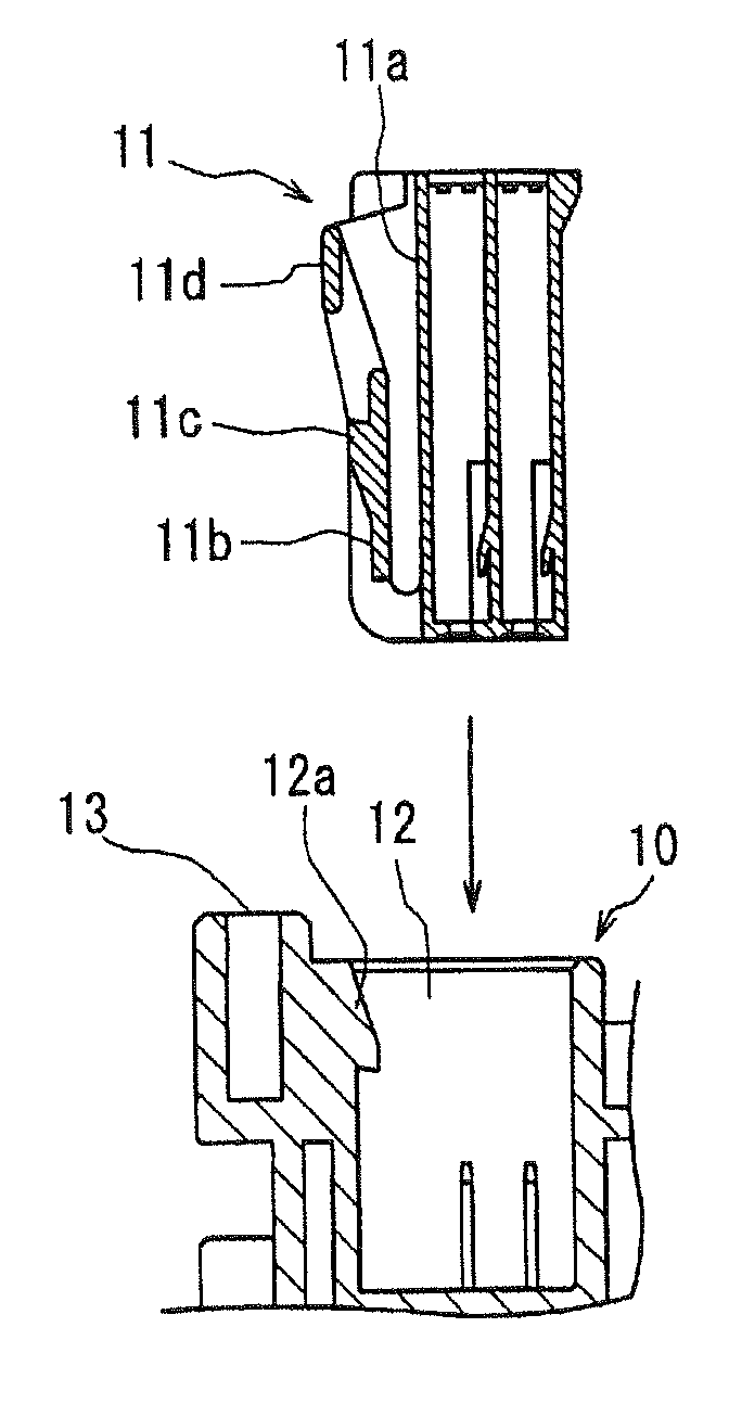
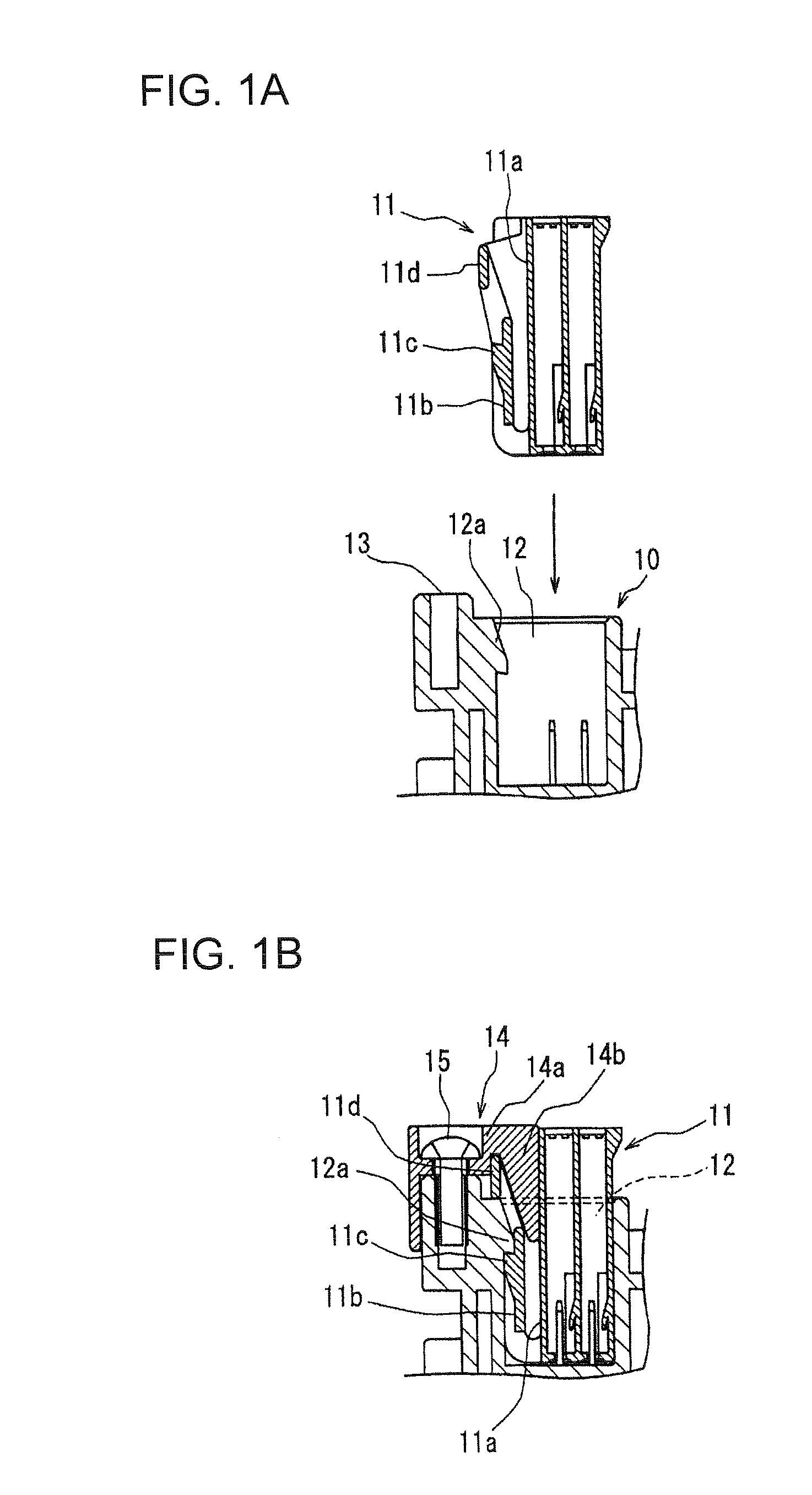
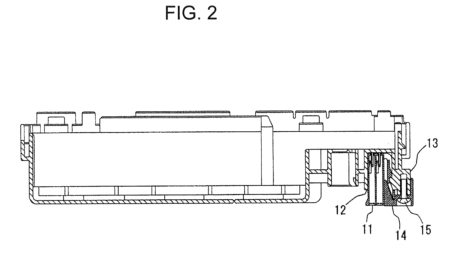
[0030]FIG. 1A through FIG. 3 show an embodiment of an extraction preventing device for a connector in accordance with the present invention.
[0031]A casing 10 of an electrical junction box to be installed in a motor vehicle is provided with a plurality (three in the present embodiment) of connector containing members 12 for receiving connectors 11. A receiving port of each connector containing member 12 is directed outward.
[0032]A connector latching projection 12a protrudes from an inner surface of each connector containing member 12. A piece being latched 11b that is flexible from a front end to a rear end in a connector inserting direction (a direction shown by an arrow in FIG. 1A) protrudes an housing outer surface 11a of each connector 11 to be fitted in each connector containing member 12. Each piece being latched 11b is provided on a rear end with a projection being latched 11c. When each connector 11 is inserted into each connector containing member 12 and each projection being latched 11c is locked on an inserting side surface of each connector latching projection 12a, the connector 11 is completely fitted in the connector containing member 12.
[0033]In the present embodiment, each connector containing member 12 is disposed on a lower surface of the casing 10 of the electrical junction box. The electrical junction box is attached to an inner panel (not shown) of a driver's seat so that a lower surface of the casing 10 is disposed at a rear side. Although the connector containing members 12 are disposed on an upper surface of the casing 10, it is possible to more surely prevent the connector 11 from being subject to unauthorized access, if the connector containing members 12 are disposed on the lower surface of the casing 10.
[0034]Also, the electrical junction box is connected to a unit related to an immobilizer (in more detail, an immobilizer unit). When the connectors 11 are extracted from the connector containing members 12 of the casings 10 and the above unit including the electrical junction box is exchanged for an alternative unit at a time, a motor vehicle can move without checking ID codes.
[0035]Also, a plurality (five in the present embodiment) of cover attaching portions 13 protrude from a peripheral edge along one side of each connector containing member 12 at a protruding side of the connector latching projection 12a and are spaced from one another. After each connector 11 is fitted into each connector containing member 12, a single cover 14 is secured to the cover attaching portions 13 by a plurality (five in the present embodiment) of screws 15 (see FIG. 1B, FIG. 2, and FIG. 3). The single cover 14 is provided with an interfering rib 14a that protrudes outward from a connector receiving port of each connector containing member 12 and with a latching holder 14b that is bent from a distal end of the interfering rib 14a and is inserted into a clearance between the housing outer surface 11a of each connector 11 and each piece being latched 11b.
[0036]The latching holder 14b is formed into the substantially same tapered shape as that of the clearance between the housing outer surface 11a of each connector 11 and each piece being latched 11b. A locking portion between the connector latching projection 12a and the projection being latched 11c is covered with the interfering rib 14a and latching holder 14b. Accordingly, a releasing jig (not shown) cannot enter the locking portion from the outside.
[0037]According to the above construction, after the connectors 11 are fitted in the connector containing members 12, the cover 14 is attached to the one side of each connector containing member 12 at each projecting side of the connector latching projection 12a. The cover 14 comprises the interfering rib 14a that protrudes outward from the receiving port and the latching holder 14b to be inserted into the clearance between the housing outer surface 11a of the connector 11 and the piece being latched.
[0038]Accordingly, it is impossible for any person to release the locking state between the projection being latched 11c and the connector latching projection 12a by pushing a lock release operating portion 11d by the person's finger. In addition, it is impossible for any person to release the locking state by inserting the releasing jig into the locking portion from the outside. Accordingly, the above construction makes it difficult to extract the connector 11 from the connector containing member 12.
[0039]When the latching holder 14b is inserted into the clearance between the housing outer surface 11a of the connector 11 and the piece being latched 11b, the piece being latched 11b is not deflected by vibrations or the like in a direction for releasing the locking position, that is, in a direction toward the housing outer surface 11a of the connector 11. Consequently, it is possible to prevent the connector 11 from being fallen down by the lock releasing operation and to enhance toughness of the connector against the vibrations or the like.
[0040]Further, as described above, since the single cover 14 comprises the interfering rib 14a that interferes with the connectors 11 fitted in the plural connector containing members 12, and the latching holder 14b, it is possible to reduce the number of parts and to enhance efficiency in attaching work of the cover 14.
[0041]Also, as described above, since the cover attaching portion 13 is provided on the peripheral edge along the one side of the connector containing member 12 at the projecting side of the connector latching projection 12a and the cover 14 is secured to the cover attaching portion 13 by the plural screws 15, in order to release the locking state between the connector latching projection 12a and the piece being locked 11c and to extract the connector 11 from the connector containing member 12, firstly the plural screws 15 must be removed from the cover attaching portion 13 one after another, and secondly the cover 14 must be removed from the cover attaching portion 13. This will make it difficult to extract the connector 11 from the connector containing member 12.
[0042]In the case where the connectors that should be difficult in extraction are juxtaposed, it will be effective to reduce the number of parts by covering the all locking portions with a single cover. However, it will be possible to increase a working time necessary for extracting the connectors, if covers are mounted on the respective juxtaposed connector containing members.
[0043]Thus, it is possible to prevent a motor vehicle from being stolen by making it difficult to extract the connector 11 from the connector containing member 12 on the casing 10 of the electrical junction box, even if the motor vehicle installs an anti-theft system such as an immobilizer.