Electrical connector

Active Publication Date: 2011-02-24
HIROSE ELECTRIC GROUP
View PDF7 Cites 7 Cited by
  • Summary
  • Abstract
  • Description
  • Claims
  • Application Information

AI Technical Summary

Benefits of technology

[0027]Furthermore, a distance between the first arm portion of the U-shape portion of the terminal and the extending portion is as little as the space formed between the extending portion of the terminal and the outer surface of the first sidewall, when the terminal is attached to the housing. Accordingly, the first sidewall enters between the one of the arm portion and the extending portion without generating a contact pressure when the terminal

Problems solved by technology

Consequently, an electric connection may be poor at the soldered portion.
Therefore, upon using the connector, an electrical conduction becomes p

Method used


Image

  • Electrical connector
  • Electrical connector
  • Electrical connector

Examples


first embodiment

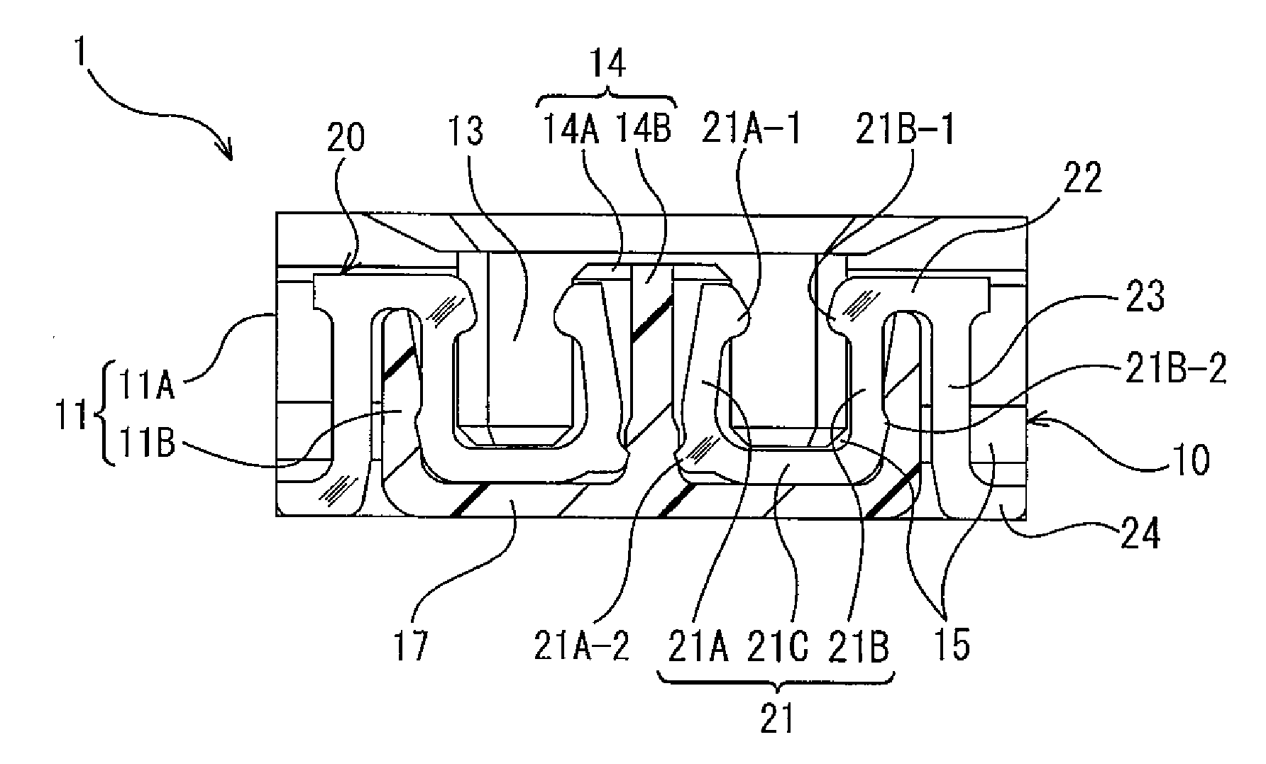
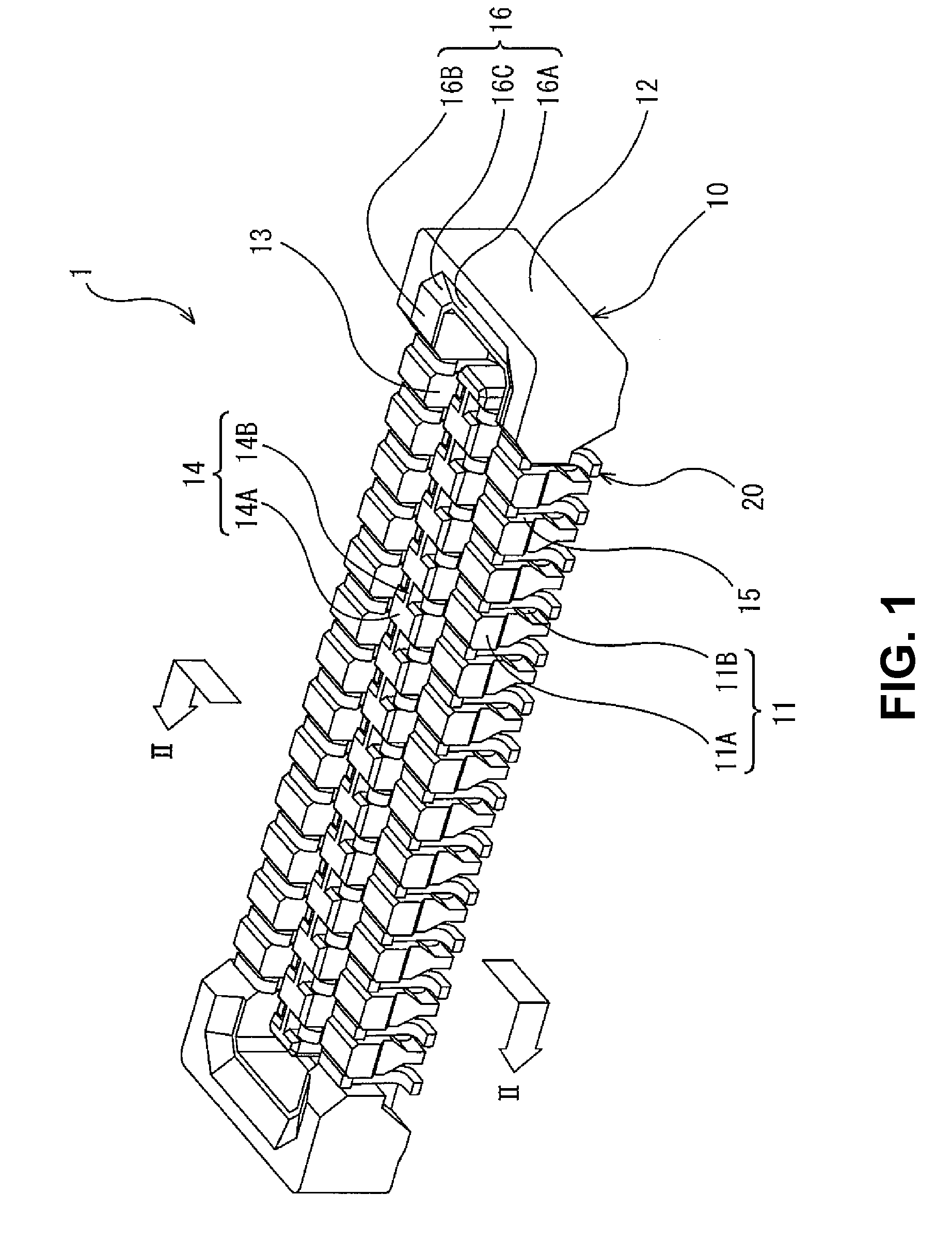
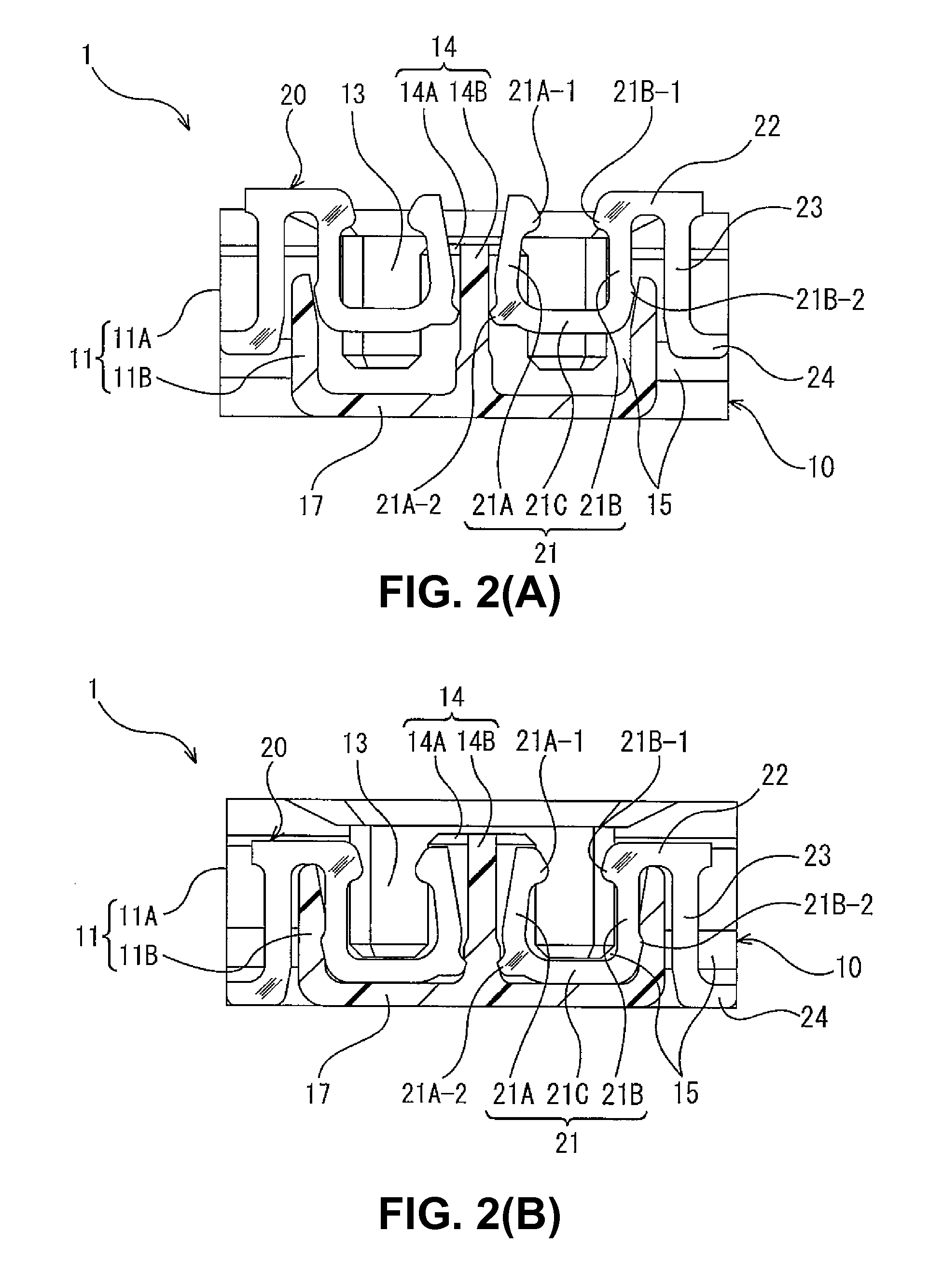
[0036]FIG. 1 is a perspective view showing an electrical connector 1 (a connector 1) for a circuit board according to an embodiment of the present invention. FIGS. 2(A) and 2(B) show an assembling process of the connector 1, wherein FIG. 2(A) shows a state that a terminal 20 is in a halfway of being attached to a housing 10, and FIG. 2(B) shows a state the terminal 20 is completely attached to the housing 10. FIGS. 2(A) and 2(B) are sectional views taken along a line II-II in FIG. 1, that is, where the terminal 20 is situated in a longitudinal direction of the housing 10.

[0037]As shown in FIG. 1, the connector 1 according to the embodiment of the present invention is to be attached to the circuit board (not shown). The connector 1 includes the housing 10 made of a synthetic resin and a plurality of the terminals 20 made of a metal plate disposed and held in the housing 10.

[0038]The housing 10 includes a receiving recess portion 13 opening in an upper direction. The connector 1 recei...

second embodiment

[0079]In the connector according to a second embodiment, the locking portion of the engaging arm portion of the terminal does not have a protruding shape while the connector in the first embodiment has the locking portion with the protruding shape in the engaging arm portion. The connector according to the embodiment has the same configuration with the connector according to the first embodiment as a basic structure. Accordingly, the components in the embodiment will be given reference numerals adding 100 to the reference numerals of the same components in the first embodiment respectively, and the explanation thereof will be omitted. Differences from the first embodiment will be mainly explained.

[0080]FIG. 5 is a sectional view showing a connector 101 according to the embodiment. As shown in FIG. 5, an engaging arm portion 121B includes an edge portion facing an inner surface of a secondary side wall portion 111B (an outside surface of a receiving recess portion 113) and extending ...

third embodiment

[0081]In the connector according to a third embodiment, the locking portion of the engaging arm portion of the terminal does not have a protruding shape while the connector in the first embodiment has the locking portion with the protruding shape of the engaging arm portion. The connector according to the embodiment has the same configuration with the connector according to the first embodiment as a basic structure. Accordingly, the components in the embodiment will be given reference numerals adding 200 to the reference numerals of the same components in the first embodiment respectively, and the explanation thereof will be omitted. Differences from the first embodiment will be mainly explained.

[0082]FIG. 6 is a sectional view showing a connector 201 according to the embodiment. As shown in FIG. 6, a contact arm portion 221A includes an edge portion facing a wall surface of a secondary central wall portion 214B (an inside surface of a receiving recess portion 213) and extending in ...


PUM


Abstract

An electrical connector includes a housing to be disposed on a circuit board, a receiving recess portion formed in the housing for receiving a mating connector, and a terminal arranged in the housing. The terminal includes a U-shape portion, an extending portion extending outside the receiving recess portion a first sidewall facing outside, and a connecting portion. The U-shape portion includes a first arm portion and a second arm portion. The first arm portion is fitted along the sidewall and the second arm portion is fitted along a second sidewall. The first arm portion and the second arm portion include locking portions for being fixed against an inner surface of the receiving recess portion, respectively. The extending portion is arranged to be away from the first sidewall to form a space in between.

Description

BACKGROUND OF THE INVENTION AND RELATED ART STATEMENT[0001]The present invention relates to an electrical connector. More specifically, the present invention relates to an electrical connector attached to a circuit board.[0002]A conventional electrical connector (a connector) is disclosed in Patent Reference. The connector for a circuit board in Patent Reference includes a housing (an insulating main body) formed with a recess portion for receiving a mating connector opening in an upper direction and a plurality of terminals held in the housing.[0003]The housing includes a convex portion situated in a central portion of the recess portion of the housing. The convex portion has an island shape and protrudes in the upper direction from a bottom wall portion as a wall portion. The recess portion surrounds the convex portion circularly upon being viewed from the upper direction. A plurality of the terminals is disposed in both ends of the convex portion along a sidewall of the housing t...

Claims


Application Information

Patent Timeline
IPC IPC(8): H01R24/00
CPCH01R12/57H01R12/716H01R13/2442
Inventor OOI, TETSUYA
Owner HIROSE ELECTRIC GROUP
Why Eureka
Try Eureka