
Energy reducing retrofit method and apparatus for a constant volume HVAC system

Active Publication Date: 2011-02-24
PRO STAR ENERGY SOLUTIONS LP
View PDF46 Cites 65 Cited by
  • Summary
  • Abstract
  • Description
  • Claims
  • Application Information

AI Technical Summary

Benefits of technology

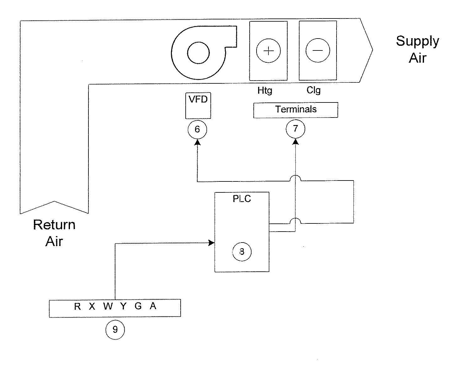
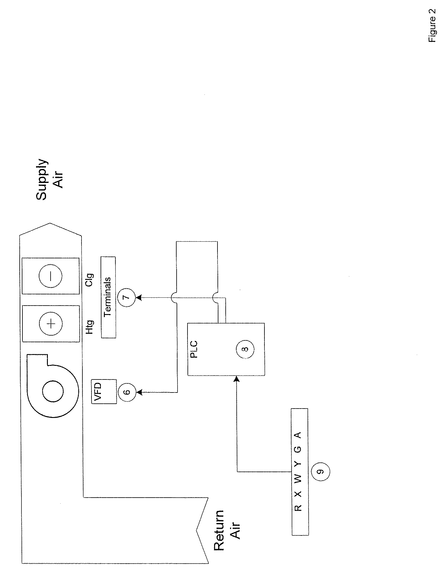
The invention works to solve many of the issues presented above by providing an enhanced programmable logic controller with a variable frequency drive capability to retrofit an existing constant volume HVAC system and mimic the efficiencies inherent in more sophisticated HVAC systems. By controlling the speed of the fan motor (and ergo the fan) to better match occupancy needs, the fan motor can be run at a significantly reduced speed in the ventilation mode. Controlling the speed of the fan motor (and ergo the fan) to maintain minimum manufacturer recommended airflow levels during the heating and cooling modes also provides a reduction in motor speed. Such reductions in the fan motor speed reduces current draw and, therefore, provide significant energy savings over prior art constant volume HVAC systems.
The method of retrofit reduces the speed of the fan motor in the ventilation, heating and cooling modes.
According to other aspects of the present invention, additional energy savings may be further achieved through integrated economization, differential economizer control, and unoccupied damper control.
The enhanced programmable logic controller and VFD may be combined in a single efficiency enhancing controller (EEC) unit that can be readily adapted to an existing constant volume system without great expense or intrusion.
The method of the present retrofit invention, and related EEC apparatus, can reduce the fan speed by up to 80% depending on occupancy demands of the building space.

Problems solved by technology

The method of retrofit reduces the speed of the fan motor in the ventilation, heating and cooling modes.

Method used


Image

  • Energy reducing retrofit method and apparatus for a constant volume HVAC system
  • Energy reducing retrofit method and apparatus for a constant volume HVAC system
  • Energy reducing retrofit method and apparatus for a constant volume HVAC system

Examples


Embodiment Construction

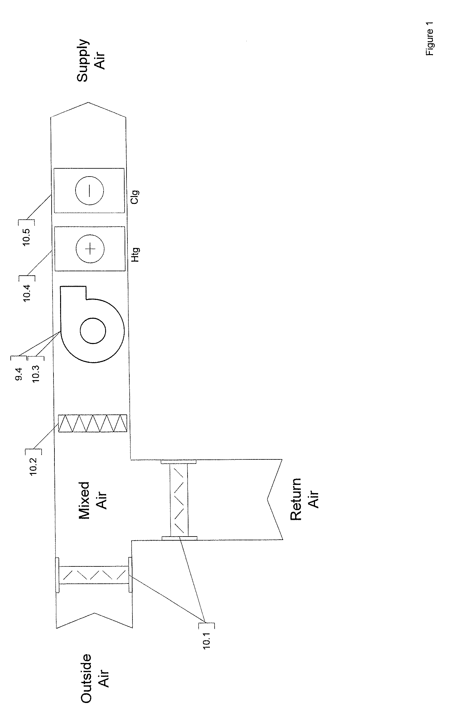
The present invention is directed to a method and apparatus for significantly reducing energy consumption of an existing constant volume HVAC system with or without an economizer. In a constant volume HVAC system the fan runs continuously at the same speed, and the volume of air being supplied to the space does not change (constant air flow rates). A thermostatic control device (most commonly a thermostat) controls the heating and cooling operations. Economizers are the arrangement of dampers that control the quantity of return air (air coming back from the space being treated) and outside air (fresh air being used for cooling or ventilation). Here, the invention involves taking control over the existing fan, cooling, and heating operation, and optional economizer of the existing system.

In contrast to a constant volume system, a variable air volume system (VAV) relies on the reduction of air flow or fan motor speed (and ergo fan speed) to attain energy savings. However, variable air...


PUM

PropertyMeasurementUnit
Fractionaaaaaaaaaa
Fractionaaaaaaaaaa
Fractionaaaaaaaaaa

Abstract

An energy-reducing method and apparatus for retrofitting a constant volume HVAC system, with or without an economizer, that provides heating, cooling, and ventilation to occupants within a building space. The present invention includes the introduction of a programmable logic controller and variable frequency drive (VFD) that takes control of the existing fan, heating, cooling, and optional economizer operation. The controller is programmed for the reduction of fan speed in the heating and cooling modes. The reduction of the fan speed in the ventilation mode when the 100% operation is not needed saves significant energy of the existing constant volume HVAC system where the fan motor is designed to run 100% of the time. The fan speed may be further reduced upon a reduction in sensed occupancy levels of the space, such as with a CO2 sensor. Additionally, the fan speed may be reduced in the heating and / or cooling mode to further reduce energy consumption. The controller may also be programmed and equipped with sensors to allow simultaneous mechanical compressor cooling and economizer free cooling operation, for the operation of the economizer in response to the monitoring of outside air and return air to determine the preferred source for cooling operations, to keep the outside air damper closed during the unoccupied heating modes such as morning warm-up, and / or to provide fault detection. The retrofit method and apparatus may be employed in a stand-alone or networked version.

Description

TECHNICAL FIELDThe present invention relates to energy saving improvements to constant volume HVAC systems, particularly, the invention relates to the retrofit method and apparatus in order to control and reduce energy consumption through the use of an efficiency enhancing controller, a variable frequency drive, and an optional occupancy sensor.BACKGROUND OF THE INVENTIONHVAC (Heating, Ventilation, & Air Conditioning) systems are used to meet occupant comfort and ventilation needs within a building space. Typically this involves the conditioning of air circulated to and from the space served via an air handler of some form, e.g., fans and blowers. Conditioning the air can include any combination of heating, cooling, filtering, humidifying, & dehumidifying air in a defined building space. Additionally, most HVAC systems have provision for supplying minimum amounts of fresh outside air to insure proper ventilation for human occupants.HVAC systems include constant volume systems and va...

Claims


Application Information

Patent Timeline
IPC IPC(8): G05D23/19G05B19/042B01F23/10G06F1/32
CPCF24F11/0015F24F11/0079F24F2011/0006F24F2011/0026F24F2011/0075G05B19/042G05B2219/25289G05B2219/2614G05D7/0676Y02B30/542Y02B30/78Y02B30/94H04L67/125H04L67/12G05D23/1919F24F11/006F24F2110/20F24F2110/50F24F2110/70F24F11/62F24F11/46F24F11/30F24F11/77Y02B30/54F24F11/58Y02B30/70Y02B30/90G05B19/05G05B2219/1133
Inventor MILLER, DANNYSIPE, JUSTIN
Owner PRO STAR ENERGY SOLUTIONS LP
Learn More