Exhaust gas purification apparatus

a technology of exhaust gas and purification apparatus, which is applied in the direction of mechanical apparatus, engine components, machines/engines, etc., can solve the problems of increasing the length of the apparatus and the difficulty of making it small

Inactive Publication Date: 2011-03-03
TOYOTA IND CORP
View PDF7 Cites 12 Cited by
  • Summary
  • Abstract
  • Description
  • Claims
  • Application Information

AI Technical Summary

Problems solved by technology

The exhaust gas purification apparatus including the urea SCR system and the DPF has many components provided between the engine and the muffler and requires a large space for mounting of such components to a vehicle.
Therefore, there has been problems in that the apparatus increases its length and it is difficult to make it small.

Method used


Image

  • Exhaust gas purification apparatus
  • Exhaust gas purification apparatus
  • Exhaust gas purification apparatus

Examples


Embodiment Construction

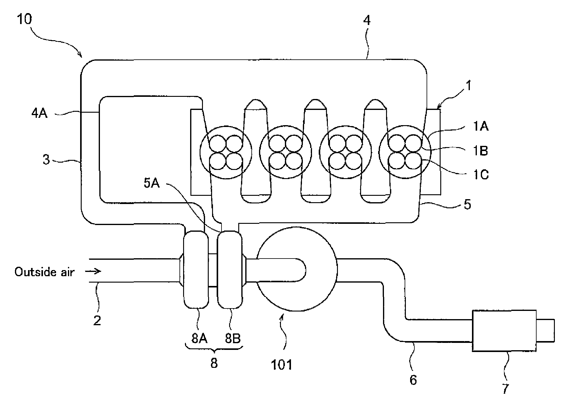
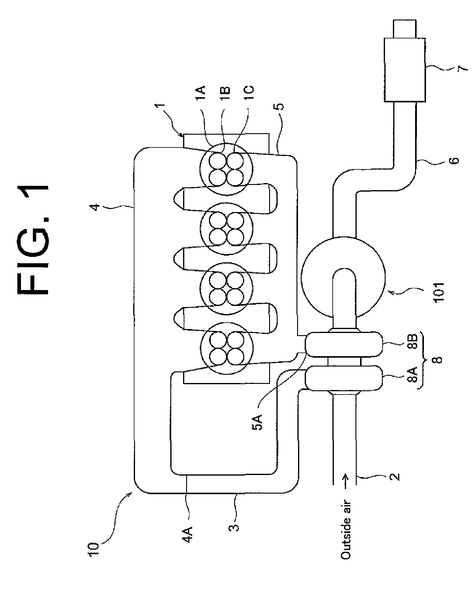
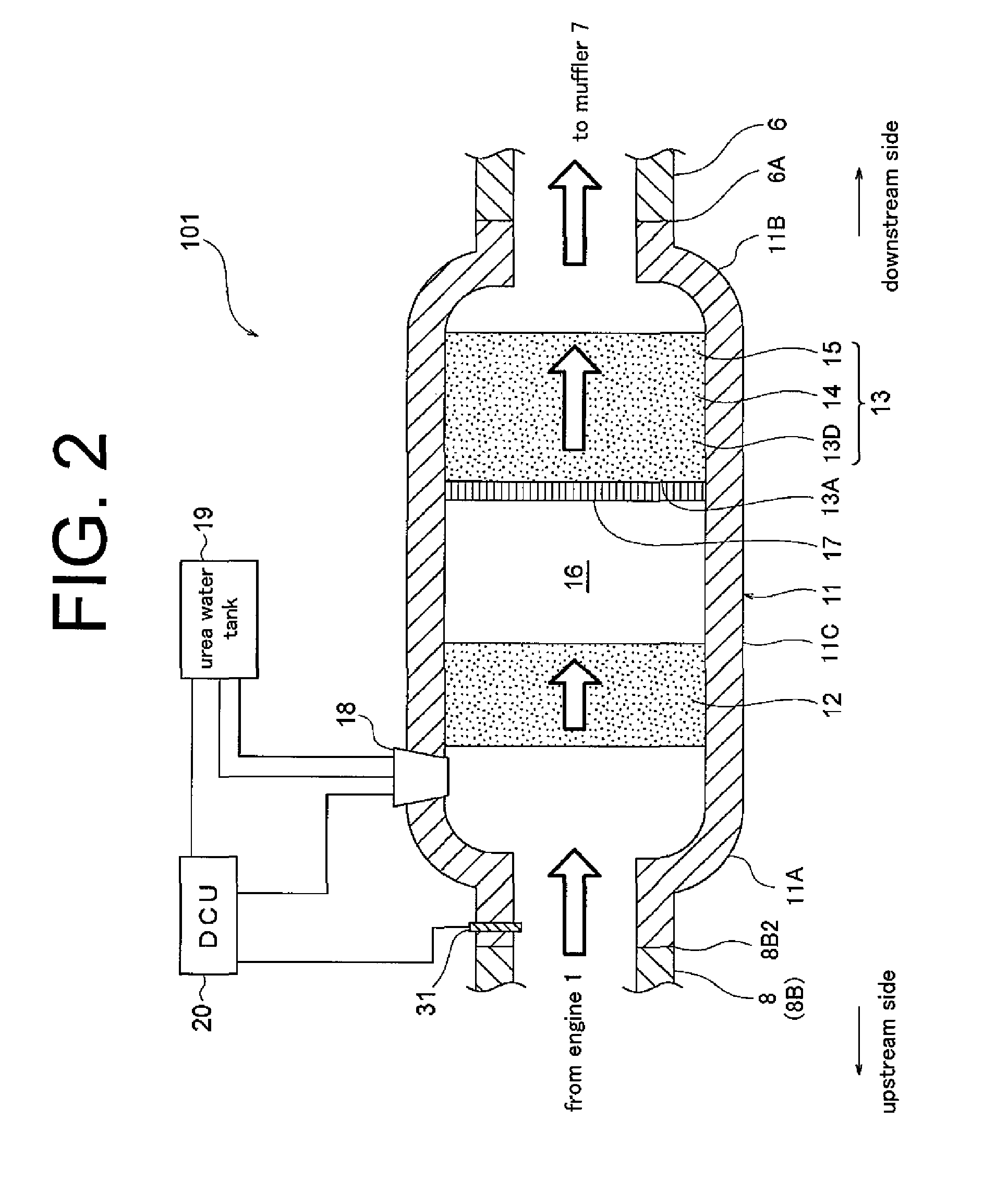
[0014]The following will describe the embodiment of the exhaust gas purification apparatus according to the present invention with reference to the accompanying drawings. Referring to FIGS. 1 and 2 showing the embodiment, the exhaust gas purification apparatus which is designated generally by reference numeral 101 and its associated components will be described. The exhaust gas purification apparatus 101 is employed in a vehicle equipped with a diesel engine.

[0015]Referring to FIG. 1, an engine assembly including an engine 1 and the exhaust gas purification apparatus 101 is designated generally by reference numeral 10. The engine 1 has a plurality of cylinders 1A each having an intake port 1B to which an intake manifold 4 is connected for distributing intake air to the respective cylinders 1A. The intake manifold 4 has an inlet 4A to which an engine intake pipe 3 is connected and the engine intake pipe 3 is further connected to a compressor housing 8A of a turbocharger 8. The compre...


PUM


Abstract

An exhaust gas purification apparatus includes a first oxidation catalyst provided in a passage through which exhaust gas flows, a particulate matter collecting device provided downstream of the first oxidation catalyst, a selective catalytic reduction catalyst integrally formed with the particulate matter collecting device and having ammonia adsorption property, a second oxidation catalyst integrally formed with the particulate matter collecting device and oxidizing ammonia at a predetermined temperature or higher and a urea water supply device provided upstream of the selective catalytic reduction catalyst for supplying urea water. The urea water supply device supplies urea water only when a temperature of the second oxidation catalyst is below the predetermined temperature.

Description

BACKGROUND OF THE INVENTION[0001]The present invention relates to an exhaust gas purification apparatus and, more specifically, to an exhaust gas purification apparatus having a urea SCR (selective catalytic reduction) system for reducing nitrogen oxides (NOx) in exhaust gas emitted from a diesel engine.[0002]The urea SCR system has been developed for reducing NOx in exhaust gas emitted from a diesel engine. The urea SCR system employs an SCR catalyst for converting NOx into nitrogen (N2) and water (H2O) by chemical reaction between NOx and ammonia (NH3) generated by hydrolysis of urea water.[0003]The SCR catalyst is provided in the exhaust passage between the engine and the muffler. Furthermore, an oxidation catalyst and an injection valve for injecting urea water into exhaust gas are provided upstream of the SCR catalyst. The oxidation catalyst oxidizes hydrocarbons (HC) and carbon monoxide (CO) in exhaust gas into water (H2O) and carbon dioxide (CO2) and also promotes the oxidati...

Claims


Application Information

Patent Timeline
Patent Type & Authority Applications(United States)
IPC IPC(8): F01N3/035F01N3/10
CPCF01N3/035F01N3/208F01N2560/06F01N2570/10F01N13/0093F01N2610/02F01N2900/1602Y02T10/24F01N13/0097F01N2570/14Y02A50/20Y02T10/12
Inventor KATO, YOSHIFUMI
Owner TOYOTA IND CORP
Why Eureka
Try Eureka