Hand-tool system for installing blind fasteners

a blind fastener and tool system technology, applied in the direction of manufacturing tools, forging press details, forging presses, etc., can solve the problem of increasing hand effort, achieve the effect of reducing hand effort, reducing force output, and quick retraction of pistons

Active Publication Date: 2011-03-03
SPS TECH LLC
View PDF17 Cites 16 Cited by
  • Summary
  • Abstract
  • Description
  • Claims
  • Application Information

AI Technical Summary

Benefits of technology

[0016]In order to overcome the stated problems and provide a tool that meets the current expectation, there is provided an improved hand operated hydraulically powered tool for installing blind fasteners. In general, the tool comprises a stationary housing with an internally threaded adaptor and a moveable externally threaded piston rod. Any type of suitable pulling heads may be easily mounted to the threaded end of the tool, making the tool very versatile. Although not the subject of this invention, the pulling head used with this tool is comprised by a stationary sleeve threaded into the adaptor, having a nose-piece appropriate to the fastener to be installed and a drawbar with stem gripping means threaded onto the moveable piston rod. To pull the fastener stem through the sleeve in order to complete its installation, pressurized fluid is sent to a piston pressure chamber causing the piston to retract in relation to the housing and adaptor. Pressure is created by squeezing a lever towards the tool handle multiple times until the fastener installation is completed. The tool is operated initially in a low pressure mode, at which a rapid retraction of the piston is assured with each pump. During this stage, a faster piston travel ensures a minimum number of pumps (squeezes) for a desired piston travel. Also, a lower level of pressure is established in the piston chamber, developing a relatively low force output. The hand effort increases as the fastener installation load increases but it is limited at a ...

Problems solved by technology

The hand effort increases as the fastener installation load increases but it is limited at a ...

Method used


Image

  • Hand-tool system for installing blind fasteners
  • Hand-tool system for installing blind fasteners
  • Hand-tool system for installing blind fasteners

Examples


example 2

[0098 shows the installation curve of a flaring type fastener, also referred to as wire draw rivets. Initially, the installation load increases as the stem 931 is pulled through stationary sleeve 934. After an initial load increase, the load stabilizes rising only slightly throughout the fastener installation; this type of fastener also tends to require long displacement and low installation load. The load peaks when the installation is completed.

[0099]Example 3 shows a fastener with a more complex installation curve. After an initial peak (above 1000 Lbs in the example) dips to about 600 Lbs, peaks again at 1400 Lbs and dips to about 200 Lbs before completing the fastener installation at around 1600 Lbs.

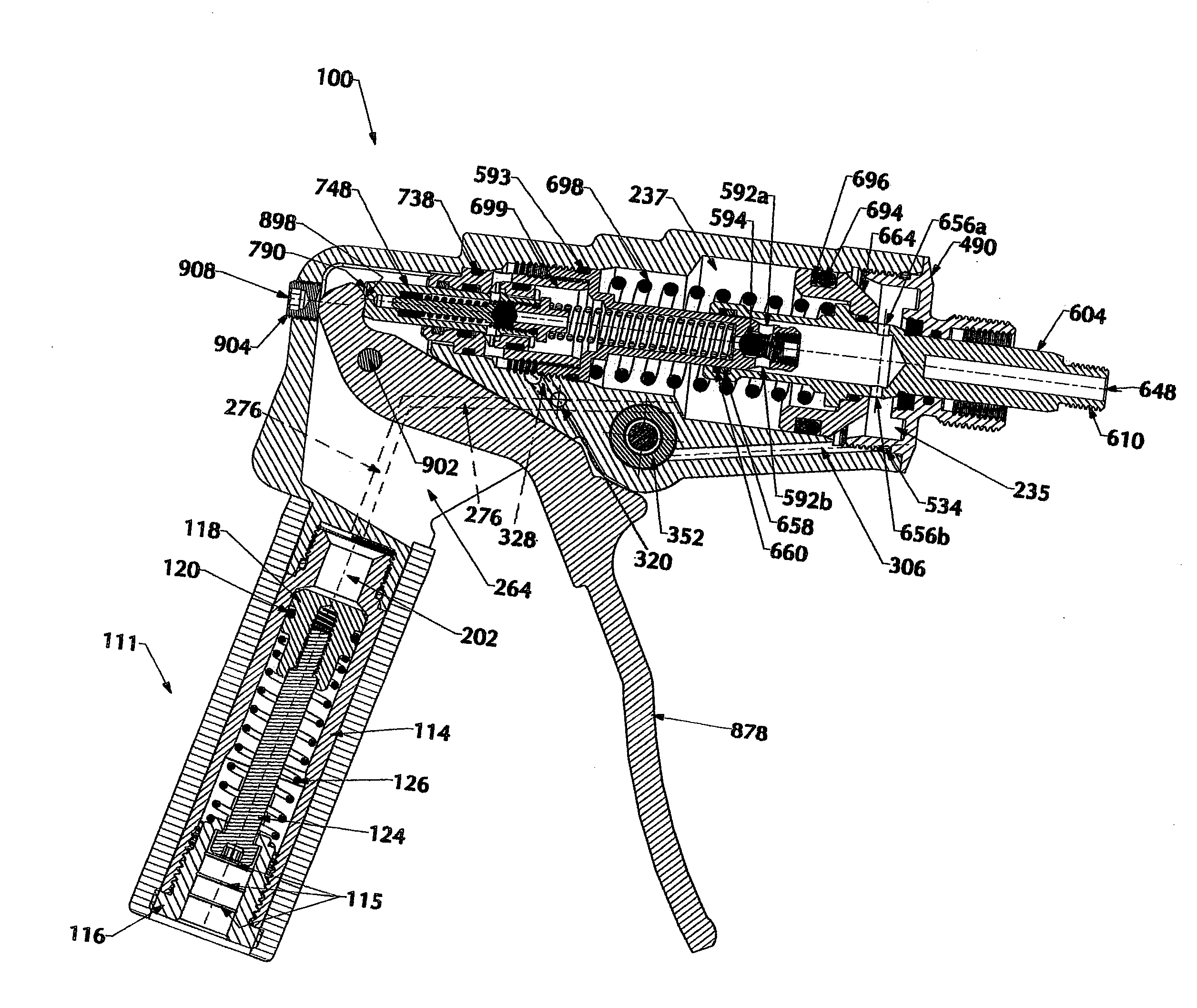
[0100]When installing a blind fastener with the tool 100, after a few squeezes of the lever 878 the pressure inside of the tool 100 increases to a level that would require such a high hand effort that could not be achieved by the operator even if using both hands. That is when the t...


PUM

PropertyMeasurementUnit
Forceaaaaaaaaaa
Pressureaaaaaaaaaa
Levelaaaaaaaaaa

Abstract

A tool for setting blind fasteners is disclosed. A stem of a fastener is engaged by a pulling head and its sleeve is also engaged by the pulling head. In an initial stage, a pump piston compresses fluid in a hydraulic pump, affecting movement of a drawbar and piston in relation to a stationary adaptor connected to the tool, pulling the stem in relation to the sleeve at a fast rate per pump. As the pulling force increases, pressure in the pump triggers a logic system to shift the tool into a high pressure mode, decreasing the effort to complete fastener installation. The logic system resets after each squeeze of the lever, minimizing the number of pumps necessary to complete the installation while keeping effort at a comfortable level. An adjustable pressure relief valve allows the fluid to return to the reservoir chamber, returning the tool to its initial condition.

Description

CROSS-REFERENCE AND INCORPORATION BY REFERENCE[0001]This patent application claims the benefit of domestic priority of U.S. Provisional Application Ser. No. 61 / 237,979, filed Aug. 28, 2009, and entitled “Hand-Tool System for Installing Blind Fasteners”. U.S. Provisional Application Ser. No. 61 / 237,979 is hereby incorporated by reference.FIELD OF THE INVENTION[0002]This disclosure relates to tools used for, but not limited to, the installation of fasteners which are accessible from only one side, often called blind rivets. More specifically, the disclosure relates to a lightweight and compact hand-operated tool which uses a hydraulically powered piston to pull the stem of a blind rivet through a sleeve, whereby the fastener is set in a work-piece.BACKGROUND OF THE INVENTION[0003]Blind rivets or fasteners are of the type used when only one side of the work-piece is accessible. In such fasteners, a stem and a sleeve are inserted as a unit into aligned openings in work-pieces. The sleev...

Claims


Application Information

Patent Timeline
IPC IPC(8): B21J15/20B21J15/30
CPCB21J15/043Y10T29/53743B21J15/285B21J15/205
Inventor COBZARU, CRISTINEL OVIDIU
Owner SPS TECH LLC
Why Eureka
Try Eureka