Retractable wind energy rotor

A retractable, rotor technology, applied in wind power generation, energy industry, wind turbines, etc., can solve the problems of easy occurrence of danger, hinder cargo ship loading and unloading, occupation, etc., to facilitate installation and dismantling, reduce adverse effects, prevent the effect of destruction

Pending Publication Date: 2018-06-01
CSIC SHANGHAI MARINE ENERGY SAVING TECH DEV CO LTD
View PDF1 Cites 7 Cited by
  • Summary
  • Abstract
  • Description
  • Claims
  • Application Information

AI Technical Summary

Problems solved by technology

[0004] The Flettner rotor can use wind energy to generate thrust to move the ship forward. However, in order to generate greater thrust, the size of the rotor is often large, and the actual height of the rotor installed on the deck reaches about 20 meters, which brings many inconveniences: it hinders the loading and unloading of cargo ships Goods; when the wind direction is unfavorable, it will produce greater resistance; it is prone to danger in bad sea conditions; it is not easy to pass bridges and other facilities
[0005] Patent No. US 2016 / 0332712 A1 discloses a retractable offshore propulsion system, which uses a mechanical mechanism so that the rotor can shrink in the length direction, and the entire rotor can be retracted into the hull when necessary. This structure is too complicated and Will take up more space inside the cabin

Method used


Image

  • Retractable wind energy rotor
  • Retractable wind energy rotor
  • Retractable wind energy rotor

Examples


Embodiment Construction

[0020] The specific embodiment of the present invention will be described in detail below in conjunction with accompanying drawing, this embodiment is only used to illustrate the present invention and is not intended to limit the scope of the present invention, and those skilled in the art all fall within the present invention to the modification of various equivalent forms of the present invention The scope of the application is defined by the appended claims.

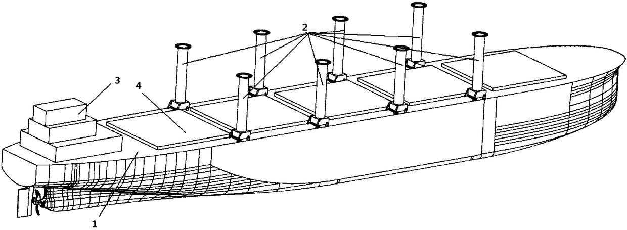
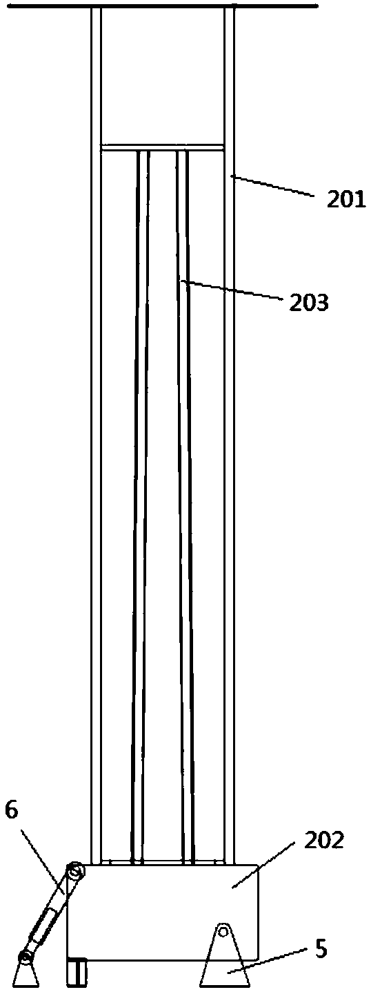
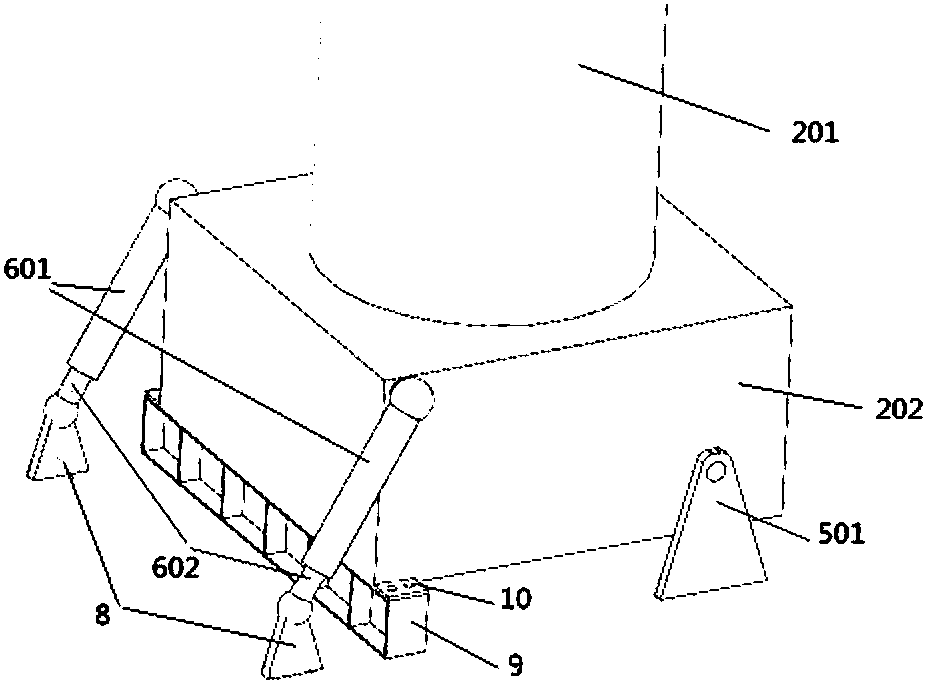
[0021] The wind energy rotor body of the present invention is composed of three parts: a stator, a rotor and a base. Both sides of the base are movably connected with the support, and the support is fixedly installed on the deck of the ship. The piston rods of the two hydraulic cylinders are hinged to the hull, and the cylinder body is hinged to the base. The stator is fixedly installed on the base. The lower part of the drum is connected with the stator and the base through bearings, and the upper part is connected...


PUM


Abstract

A retractable wind energy rotor for ship boosting is composed of a stator, a rotating barrel and a base. The base is placed on supports located on a ship deck. The stator is fixedly mounted on the base. The rotating barrel is connected with the stator and the base through bearings. A drive motor is arranged in the base. The rotating barrel is driven by the drive motor to rotate around the stator.Due to the Magnus effect, the wind energy rotator generates thrust enabling a ship to advance under the function of lateral wind. Two hydraulic cylinders are arranged outside the base, the two ends ofthe hydraulic cylinders are connected with the ship deck and the base correspondingly, and a remote console is arranged in a cab. A hydraulic system is arranged in the base and is controlled to workthrough the remote console located in the cab. The rotor is pushed by hydraulic rods to move around the supports, and therefore the rotor can be put away and released. When the rotor normally rotatesto work, the base of the rotor is locked through a mechanical method, and stable running of the stator is guaranteed.

Description

technical field [0001] The invention relates to a ship wind energy boosting device, in particular to a retractable wind energy rotor. Background technique [0002] In recent years, global climate warming has become more and more significant, and greenhouse gas emissions have attracted the attention of countries all over the world. Under the general trend of global energy conservation and emission reduction, ship energy-saving and emission-reduction technology has become a hot research topic in the field of ships. The International Maritime Organization (IMO) has also continuously introduced mandatory conventions and norms to strengthen the protection of the marine environment and the atmospheric environment. The 70th meeting of MEPC suggested adopting higher design requirements and a larger reduction rate in 2020, and even considered advancing the implementation time of Phase III. Therefore, research on new methods and technologies for energy-saving and emission-reduction o...

Claims


Application Information

Patent Timeline
Patent Type & Authority Applications(China)
IPC IPC(8): F03D13/20F03D9/32F03D80/00B63H9/00
CPCB63H9/00F03D9/32F03D13/20F03D80/00Y02E10/72Y02E10/728Y02P80/10
Inventor 郭峰山夏灏超黄树权黄振宇陈雷强黄国富吴赞李鹏程严周广张宁
Owner CSIC SHANGHAI MARINE ENERGY SAVING TECH DEV CO LTD
Why Eureka
Try Eureka