Ring type hydraulic tensioner

Inactive Publication Date: 2005-12-08
TSUBAKIMOTO CHAIN CO
View PDF6 Cites 8 Cited by
  • Summary
  • Abstract
  • Description
  • Claims
  • Application Information

AI Technical Summary

Benefits of technology

[0009] The tensioner is capable of applying proper tension to a timing chain or the like in the same manner as the conventional tensioner. However, when the plunger receives an impact from the timing chain upon engine start-up, the sliding resistance between the split ring and the inner circumferential wall of the plunger-accommodating hole against which the ring is resiliently biased, blocks rapid retraction of the plunger, preventing backlash noise. However, the ring allows

Problems solved by technology

However, when the plunger receives an impact from the timing chain upon engine start-up, the sliding resistance between the split ring and the inner circumfer

Method used


Image

  • Ring type hydraulic tensioner
  • Ring type hydraulic tensioner
  • Ring type hydraulic tensioner

Examples


Embodiment Construction

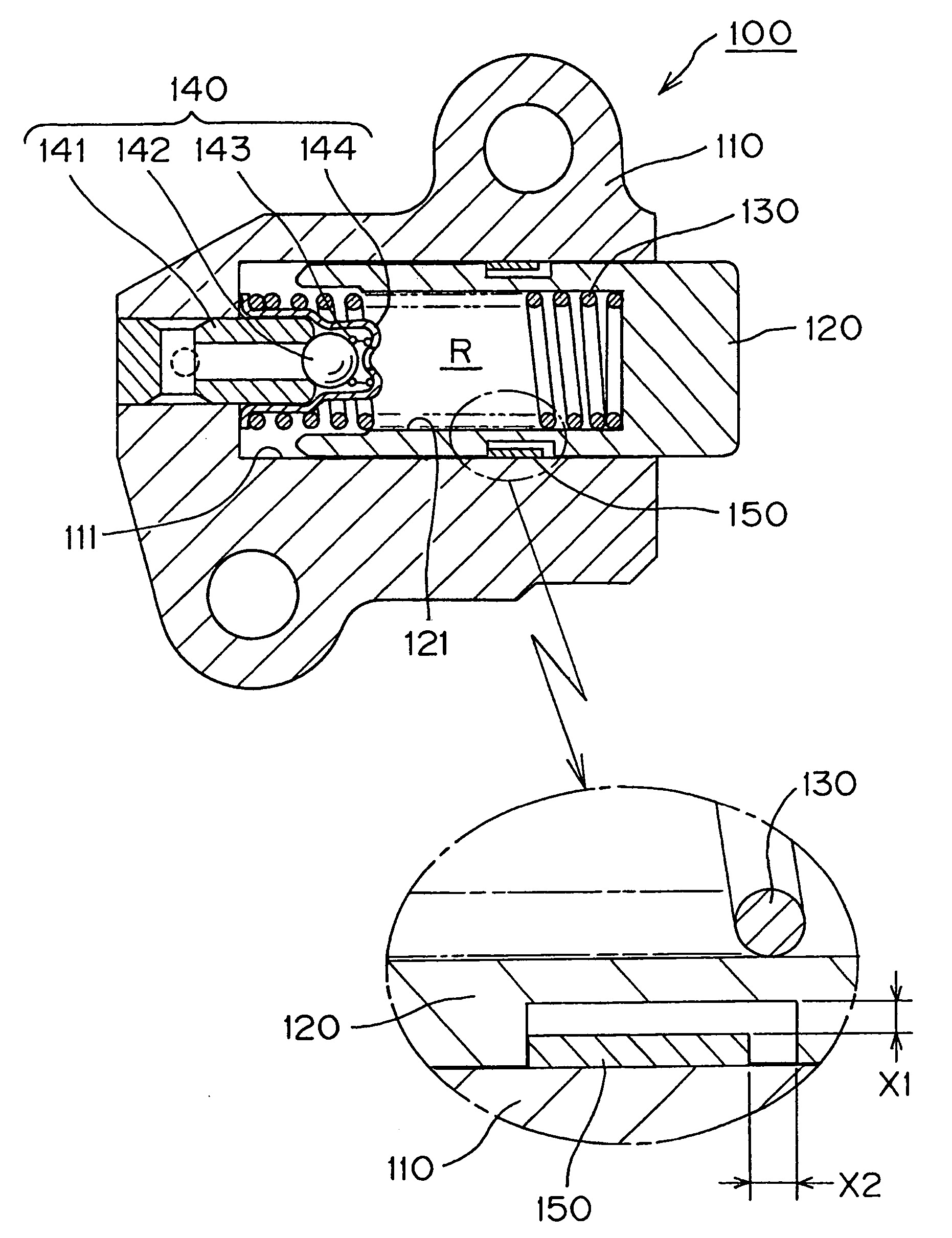
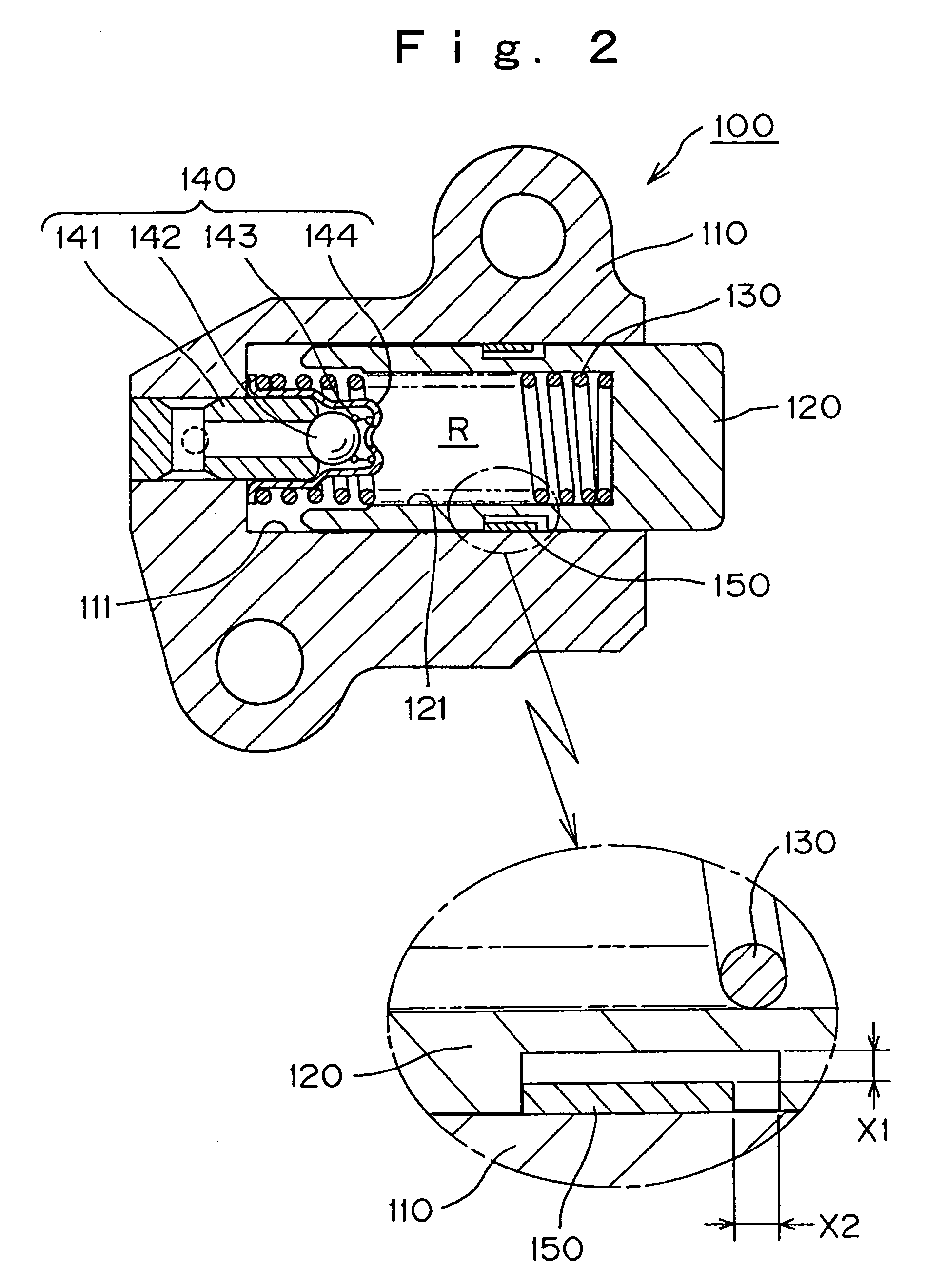
[0018] When an impact is applied to the plunger by the timing chain upon engine start-up, the tensioner in accordance with the invention prevents backlash noise by means of a simple backstop mechanism which comprises a resilient, C-shaped, split ring, which fits into an annular circumferential groove in the plunger of the tensioner with both axial and radial clearances. The ring is resiliently biased toward the inner circumferential wall of the plunger-accommodating hole in the tensioner housing. The invention is applicable to various kinds of tensioners. For example, the tensioner can be an outwardly mounted tensioner, mounted on the outside of an engine block, or an internally mounted tensioner, incorporated into an engine inside the engine block.

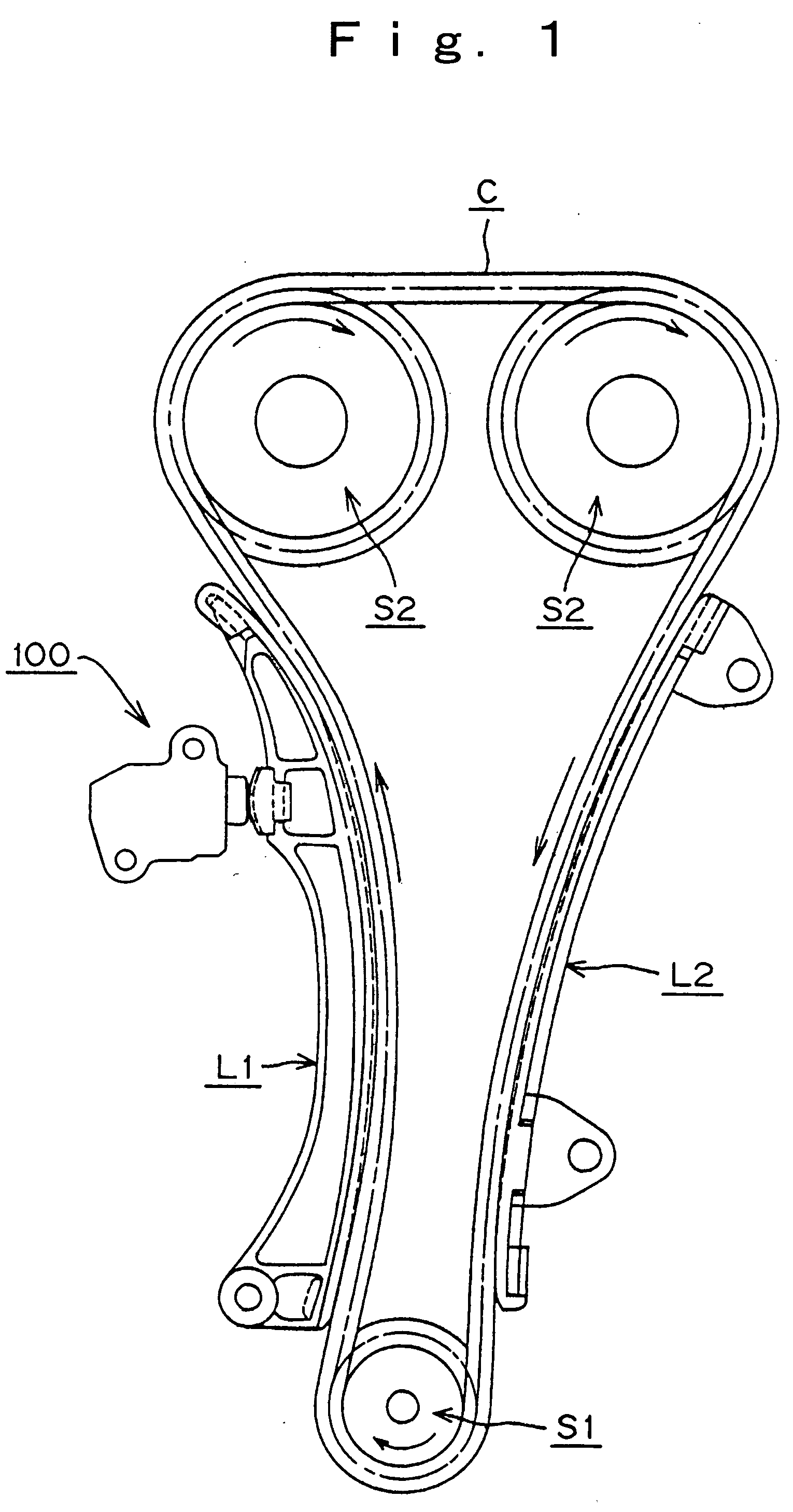
[0019] As shown in FIGS. 1-3, a ring type hydraulic tensioner 100, in accordance with a first embodiment of the invention, is attached to an engine (not shown) adjacent the slack side of a timing chain C. The chain is driven by a cranksh...


PUM


Abstract

In a hydraulic tensioner a cylindrical plunger slidably protrudes from a plunger-accommodating hole in a tensioner housing. A check valve unit allows oil to flow under pressure into a high pressure chamber formed by the plunger and the housing, but blocks reverse flow. The plunger is biased in the protruding direction by a spring located in the high pressure chamber. The plunger has an annular groove in its outer circumferential surface, and a C-shaped ring disposed in the groove is resiliently biased radially outwardly against the inner circumferential wall of the plunger-accommodating hole. A radial clearances is provided between the ring and the bottom of the groove, and the ring also fits into the groove with an axial clearance.

Description

FIELD OF THE INVENTION [0001] This invention relates to hydraulic tensioners of the kind used for maintaining proper tension in timing chains of internal combustion engines. It relates more particularly to an improved tensioner structure for preventing impact noise during engine start-up. BACKGROUND OF THE INVENTION [0002] Hydraulic tensioners have been widely used to maintain tension in power transmission media such as timing chains, used for transmitting rotation from the crankshaft to one or more camshafts in an internal combustion engine. The tensioners not only maintain proper tension in the transmission medium, but also prevent vibration. A typical hydraulic tensioner is depicted and described in Japanese Patent Publication No. 3226037 (pages 1 and 2, FIG. 6). [0003] As shown in FIG. 7, in a conventional hydraulic tensioner 500, a cylindrical plunger 520 is slidable in a plunger-accommodating hole 511 formed in a housing 510. A plunger-biasing spring 530, in compression betwee...

Claims


Application Information

Patent Timeline
IPC IPC(8): F01L1/02F16H7/22F16H7/08F16H7/00
CPCF16H7/0836F16H2007/0806F16H2007/0812F16H2007/0859F16H7/0848
Inventor YOSHIDA, OSAMU
Owner TSUBAKIMOTO CHAIN CO
Why Eureka
Try Eureka