Engine with Hydraulic Variable Valve Timing

a technology of variable cam timing and hydraulic valve, which is applied in the direction of machines/engines, non-mechanical valves, couplings, etc., can solve the problems of high oil leakage between advance and retard, and the inability to adjust the timing of the opa cam, etc., to achieve the effect of improving the fuel economy and emissions performance of the vehicle, and unacceptable performan

Active Publication Date: 2011-03-03
FORD GLOBAL TECH LLC
View PDF5 Cites 9 Cited by
  • Summary
  • Abstract
  • Description
  • Claims
  • Application Information

AI Technical Summary

Benefits of technology

[0002]Internal combustion engines may use variable cam timing (VCT) to improve fuel economy and emissions performance of a vehicle. One method of variable cam timing uses an Oil Pressure Actuated device (OPA), such as a vane type cam phaser. The phaser may be controlled by an electromechanically actuated spool valve that directs oil flow to one side or the other of the vane. The performance of this device is thus dependent on oil pressure, which can be a function of engine speed and leakage through various oil subsystems. Therefore, the Oil Pressure Actuated device may have unacceptable performance at low engine speeds or when hydraulic subsystems exhibit high oil leakage.

Problems solved by technology

Therefore, the Oil Pressure Actuated device may have unacceptable performance at low engine speeds or when hydraulic subsystems exhibit high oil leakage.
For example, the base timing may be a fully retarded timing desired for engine starting, since sufficient oil pressure is typically unavailable during engine starting operation.
The inventors herein have recognized that OPA cam phasers may be particularly prone to oil leakage and slow response time when held at base timing by hydraulic actuation force controlled by the spool valve.
For the example of a cam-fed oil pressure actuated system, oil leakage may occur between the advance and retard oil passages in the cam journal bearing due to the pressure differential between the two passages.
Oil flows through the oil passages and out of the drain port in the spool valve may reduce main galley oil pressure and thus create a significant oil pressure drop in the system.

Method used


Image

  • Engine with Hydraulic Variable Valve Timing
  • Engine with Hydraulic Variable Valve Timing
  • Engine with Hydraulic Variable Valve Timing

Examples


Embodiment Construction

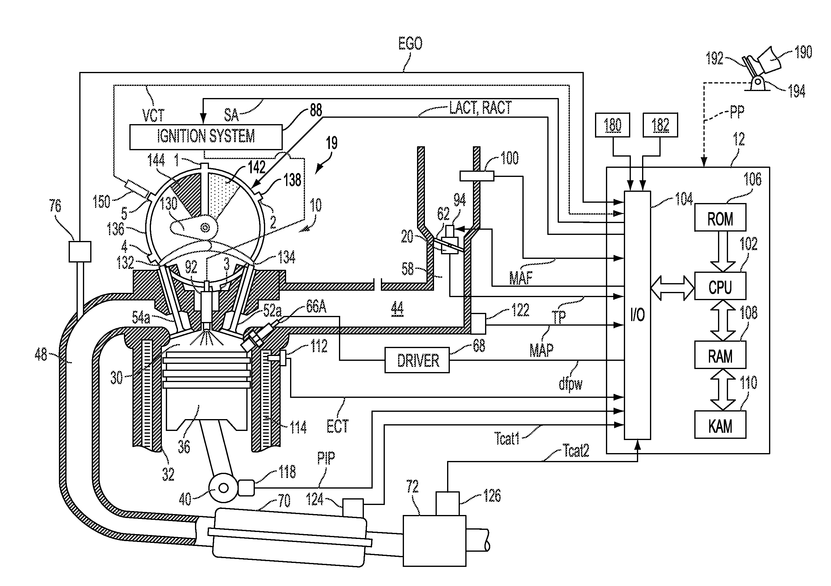
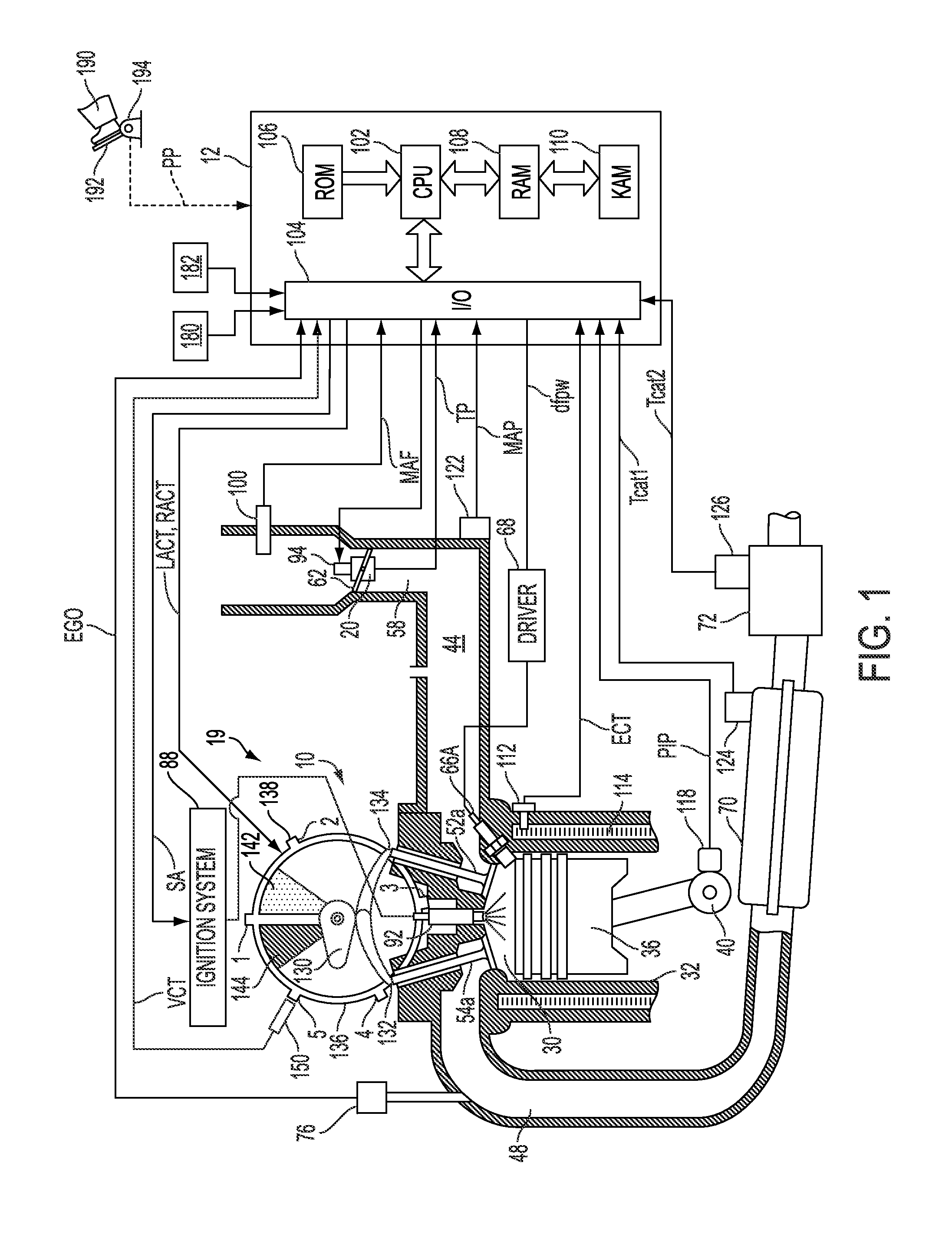
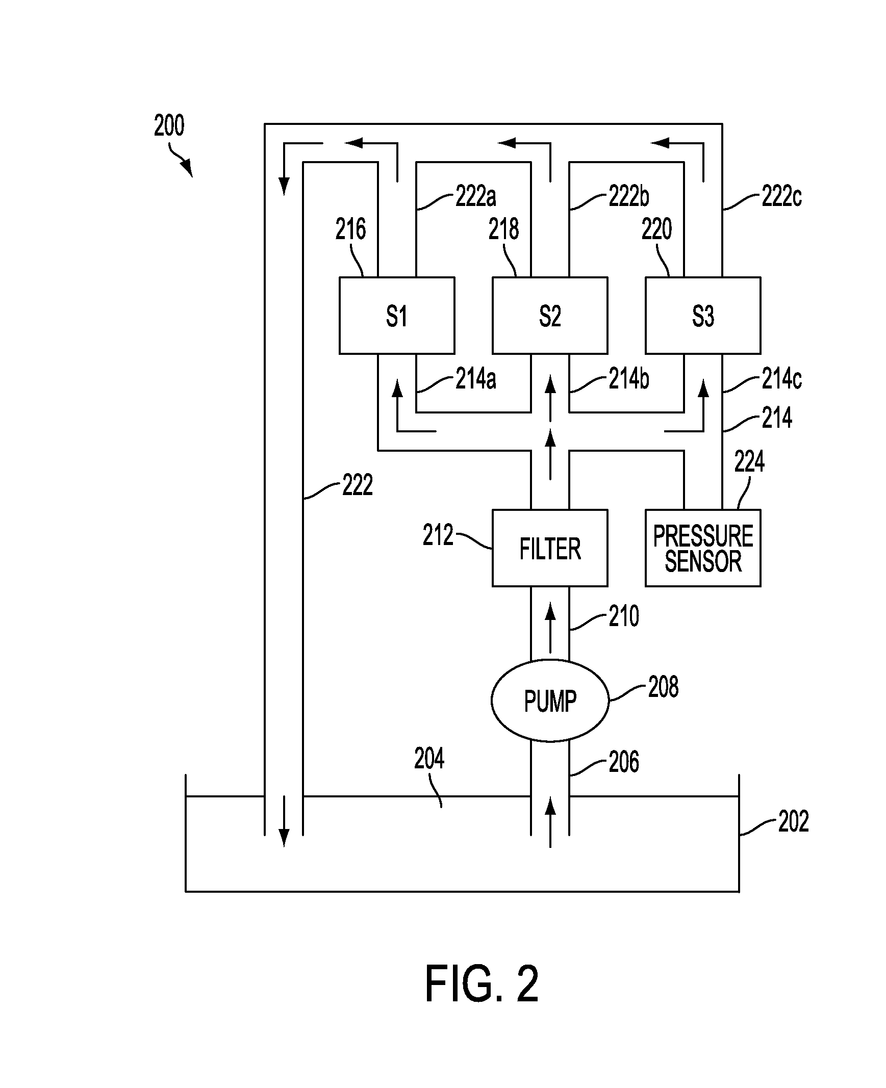
[0013]The following description relates to systems and methods for controlling an engine of a vehicle, the engine having a variable cylinder valve system, such as a variable cam timing (VCT). For example, the engine (such as the one illustrated in FIG. 1) may include a VCT phaser to adjust the cam timing (such as, an amount of cam retard or cam advance), where the phaser is included in a hydraulic system (such as described in FIG. 2). Further, the engine may include a corresponding hydraulic control system having a spool valve, as illustrated in FIGS. 3A and 3B. The hydraulic system and thus cam timing may be adjusted using a control algorithm, such as shown in FIG. 4, to reduce oil leakage and / or increase oil pressure during engine operation with the cam phaser in a base position. In one particular example, the routine includes adjusting the spool valve to a range away from a neutral / null position of the spool valve, such as illustrated in FIG. 5, during engine idling conditions wh...


PUM


Abstract

In one example, a method is described for an engine with a hydraulically actuated phaser for adjusting cam timing. The phaser is controlled by a hydraulic spool valve, for example, having a de-energized position that results in hydraulic force urging the phaser to a base timing. When it is desired to operate the cam timing at base timing, rather then leave the spool valve in a de-energized position that can generate leakage, the spool valve is adjusted to near a null position to reduce the hydraulic pressure drop across the cam journal and thus reduce oil leakage. In this way, it is possible to maintain base timing, while also reducing leakage.

Description

FIELD [0001]The present application relates to methods for operating an engine with variable cam timing (VCT).BACKGROUND AND SUMMARY [0002]Internal combustion engines may use variable cam timing (VCT) to improve fuel economy and emissions performance of a vehicle. One method of variable cam timing uses an Oil Pressure Actuated device (OPA), such as a vane type cam phaser. The phaser may be controlled by an electromechanically actuated spool valve that directs oil flow to one side or the other of the vane. The performance of this device is thus dependent on oil pressure, which can be a function of engine speed and leakage through various oil subsystems. Therefore, the Oil Pressure Actuated device may have unacceptable performance at low engine speeds or when hydraulic subsystems exhibit high oil leakage.[0003]One example VCT system includes a vane type actuator as well as an optional biasing spring to hold the cam timing in a base position whenever insufficient oil pressure is availa...

Claims


Application Information

Patent Timeline
Patent Type & Authority Applications(United States)
IPC IPC(8): F01L9/02F01L1/34
CPCF01L1/3442F01L2001/34469Y02T10/18F01L2800/00F02D13/0253F01L2001/34483Y02T10/12
Inventor CROWE, JONATHAN DENISHANSHAW, JAMIE CHARLES
Owner FORD GLOBAL TECH LLC
Why Eureka
Try Eureka