Diffraction pattern capturing method and charged particle beam device

Inactive Publication Date: 2011-03-03
HITACHI LTD +1
View PDF13 Cites 12 Cited by
  • Summary
  • Abstract
  • Description
  • Claims
  • Application Information

AI Technical Summary

Benefits of technology

[0015]According to the present invention, it becomes possible to correct the distortion (field curvature and/or a distortion occurred in a diffraction pattern plate) o

Problems solved by technology

However, a diffraction pattern generally produces deformations due to a field curvature caused by a flat detector plane, due to a distortion, and due to the external environment of the devic

Method used


Image

  • Diffraction pattern capturing method and charged particle beam device
  • Diffraction pattern capturing method and charged particle beam device
  • Diffraction pattern capturing method and charged particle beam device

Examples


Embodiment Construction

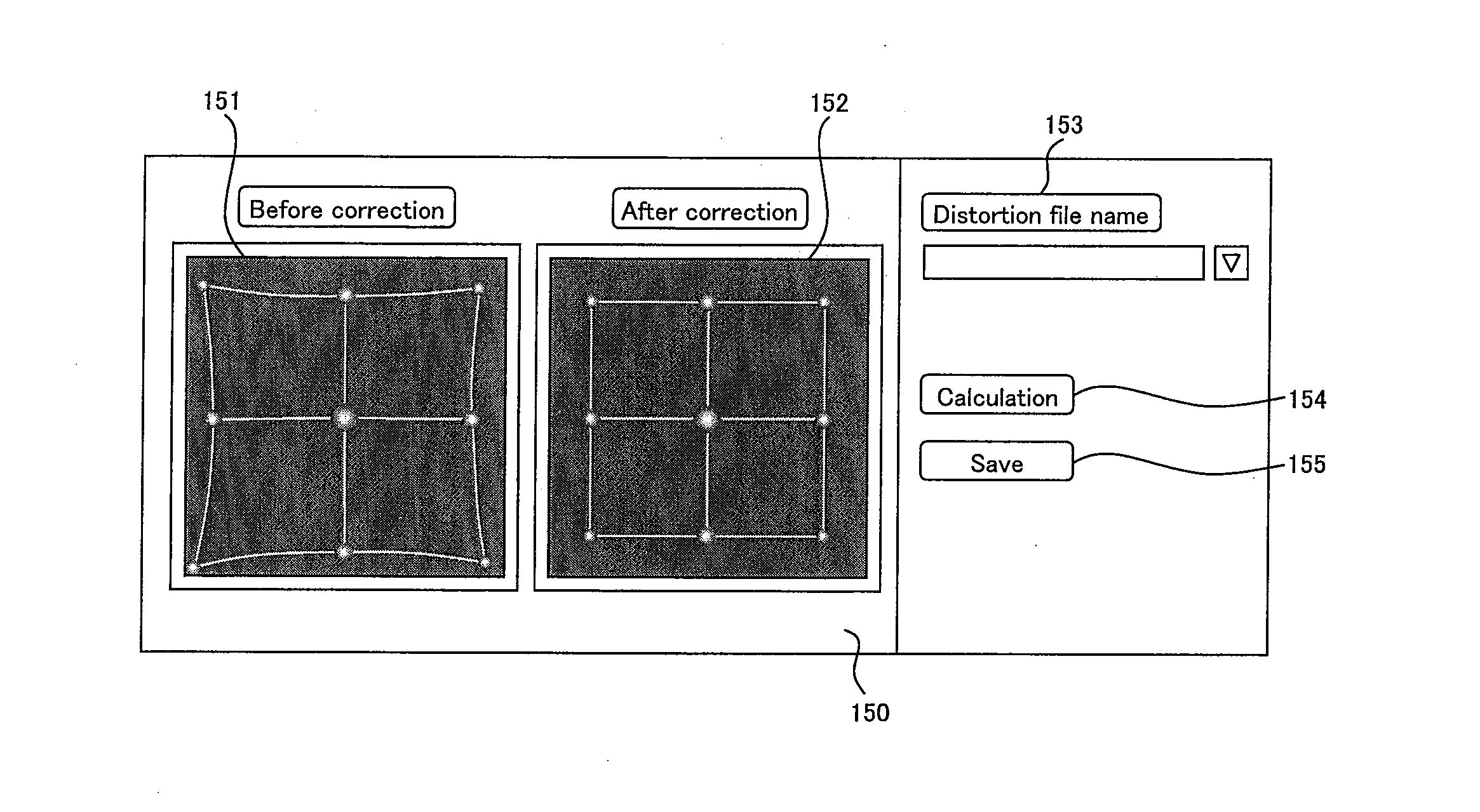
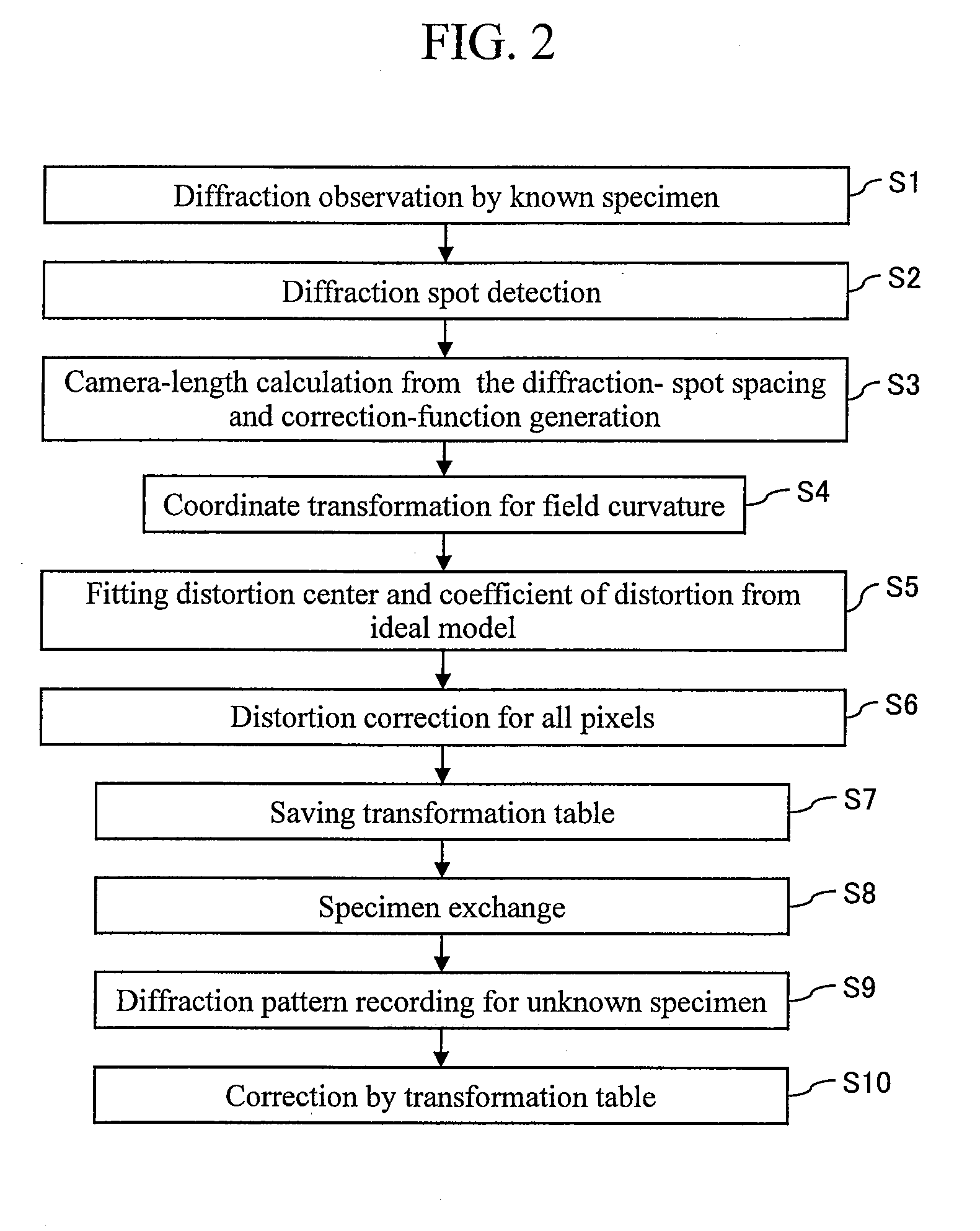
[0029]The present invention is for the purpose of calculating a correction amount for correcting a distortion of a diffraction pattern (a concept including field curvature and a distortion of the diffraction pattern plane) captured from a known sample and applying that to an unknown sample to more accurately capture a diffraction pattern of the unknown sample.

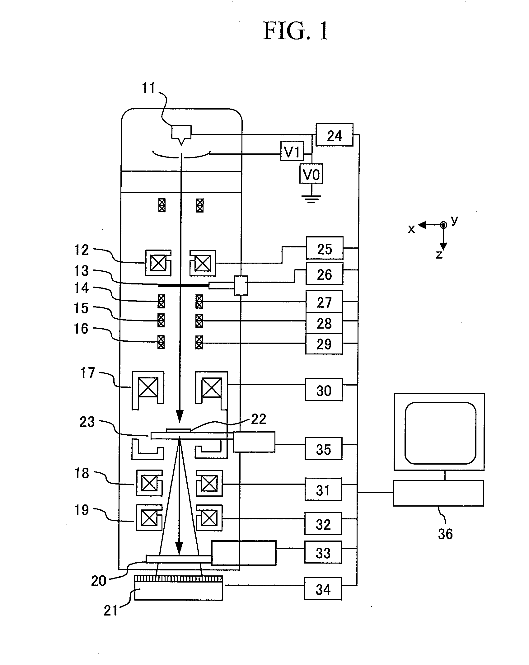
[0030]Hereafter, an embodiment of the present invention will be described with reference to appended drawings. However, it is to be noted that the present embodiment is only an example for implementing the present invention, and will not limit the technical scope of the present invention. Moreover, a common configuration in each figure is given the same reference number. It is noted that in the present embodiment, a TEM is used as the system for capturing a diffraction pattern.

[0031]The present embodiment relates to a technique for correcting a diffraction pattern obtained by a TEM, and FIG. 1 is a diagram showing a schematic c...


PUM


Abstract

A charged particle beam microscope device of the present invention is configured such that in a diffraction pattern obtained by radiating a parallel charged particle beam onto a sample (22) having a known structure, a distance (r) between spots of a diffraction pattern, which reflects the structure of the sample, is measured, and the variation of a distance (L) between the sample and a detector, which depends on a diffraction angle (θ), is corrected. This enables the correction of distortion that varies with an off-axis distance from the optical axis in a diffraction pattern, and a high precision structural analysis by performing accurately analyzing the spot positions of the diffraction pattern.

Description

TECHNICAL FIELD[0001]The present invention relates to a diffraction pattern capturing method and a charged particle beam device, and particularly, for example, to a method of capturing a diffraction pattern and a charged particle beam device, in which a charged particle beam is radiated into a sample, and a charged particle beam occurring from the sample is detected thereby capturing a diffraction pattern of the sample.BACKGROUND ART[0002]As a method of observing a diffraction pattern for the analysis of crystal structure by using an electron beam, there are a TED (Transmission Electron Diffraction), an LEED (Low Energy Electron Diffraction), and a RHEED (Reflected High Energy Electron Diffraction) methods, etc. Among those, while the LEED and RHEED methods both observe the reflection of an electron beam launched to the surface of a sample, the TED method observes an electron beam that has transmitted through the inside of a sample.[0003]Therefore, the configuration of a TED device ...

Claims


Application Information

Patent Timeline
IPC IPC(8): G01D18/00G01N23/00
CPCH01J37/222H01J2237/24578H01J37/295H01J37/26
Inventor DOBASHI, TAKASHIKOGUCHI, MASANARIKAMIMURA, OSAMUOHTA, HIROYAGOHARA, KAZUTOSHI
Owner HITACHI LTD
Why Eureka
Try Eureka