Bending LED bulb

a technology of led bulbs and led bulbs, applied in the direction of discharge tubes luminescnet screens, semiconductor devices for light sources, lighting and heating apparatus, etc., can solve the problems of increased manufacturing cost, high temperature, /b> and easy damage, etc., and achieve the effect of enhancing the illumination of the bending led bulb

Active Publication Date: 2011-03-03
LIQUIDLEDS LIGHTING
View PDF10 Cites 129 Cited by
  • Summary
  • Abstract
  • Description
  • Claims
  • Application Information

AI Technical Summary

Benefits of technology

[0014]The flexible LED strip has the LEDs mounted thereon passes through the transparent bending tube with various shapes to form the bending LED tube. As the LEDs are separately mounted on the transparent bending tube, the LEDs can be uniformly allocated in the transparent bending tube. Moreover, because the LEDs are adjacent to the wall of the transparent bending tube 10, not only can luminance of the bending LED bulb be enhanced, but also waste heat generated by the LEDs 22 can be dissipated out through the wall of the transparent bending tube 10, so as to avoid high temperature resulting from accumulation of the waste heat.

Problems solved by technology

In particular, the LEDs 322 that centrally located have a higher temperature than that of other LEDs 322 and are prone to damage.
Hence, LED bulbs or tubes with similar LED layout have to be arranged with additional heat dissipation structure and this increases the cost for manufacturing the LED bulb 30.

Method used


Image

  • Bending LED bulb
  • Bending LED bulb
  • Bending LED bulb

Examples


first embodiment

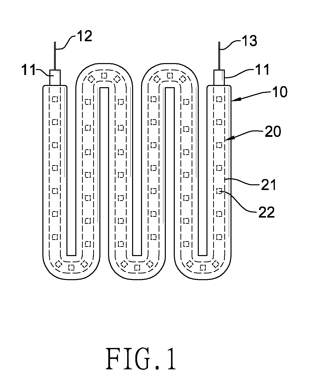
[0029]With reference to FIG. 1, a bending LED bulb has a transparent bending tube 10 and at least one flexible LED strip 20.

[0030]The transparent bending tube 10 has two sealing ends 11 and two power electrodes 12, 13. The two sealing ends 11 are respectively formed on two ends of the transparent bending tube 10. The two power electrodes 12, 13 are respectively mounted on the two sealing ends 11. In the present embodiment, the transparent bending tube 10 is alternatively and repeatedly bent up and down to have the two sealing ends facing a same direction.

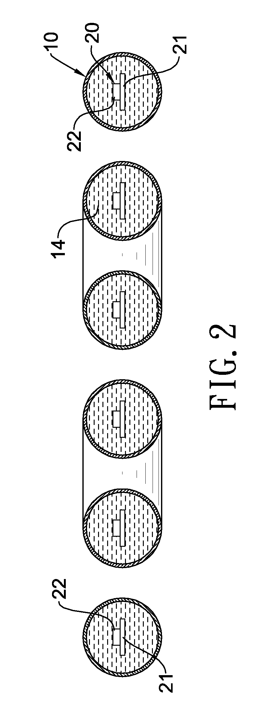
[0031]The at least one flexible LED strip 20 is received in the transparent bending tube 10, and has a flexible printed circuit board (PCB) 21 and a plurality of LEDs 22. The LEDs 22 are separately mounted on the flexible PCB 21. Both ends of the flexible PCB 21 are electrically and respectively connected with the two power electrodes 12, 13 on the two ends of the transparent bending tube 10. In an embodiment, the LEDs 22 are spaced...

second embodiment

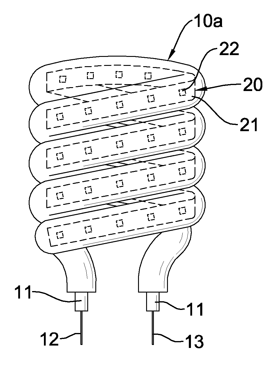
[0033]With reference to FIG. 3, in the bending LED bulb, the transparent bending tube 10a is helically wounded to take a form of a circular helix. The flexible LED strip 20 is mounted in and extends throughout the transparent bending tube 10a and is bent according to a shape of the transparent bending tube 10a to disperse the plurality of LEDs 22 in the transparent bending tube 10a.

third embodiment

[0034]With reference to FIG. 4, in the bending LED bulb, the transparent bending tube 10b is U-shaped. The flexible LED strip 20 is mounted in and extends throughout the transparent bending tube 10b and is bent according to a shape of the transparent bending tube 10b to disperse the plurality of LEDs 22 in the transparent bending tube 10b.


PUM


Abstract

A bending LED bulb has a transparent bending tube and a flexible LED strip. The flexible LED strip has a flexible printed circuit board (PCB) and a plurality of LEDs mounted on the flexible PCB and is inserted and fixed in the transparent bending tube. As the LEDs are sequentially mounted on the flexible PCB, the LEDs are adjacent to a wall of the transparent bending tube, and are equally spaced. Accordingly, a lumen value of the bending LED bulb can be raised, and heat generated by the LEDs can be dissipated out through the wall of the transparent bending tube to avoid high temperature arising from accumulation of the waste heat.

Description

BACKGROUND OF THE INVENTION[0001]1. Field of the Invention[0002]The present invention is related to an LED bulb, and more particularly to a bending LED bulb that can provide uniform luminance and dissipate out heat generated by LEDs.[0003]2. Description of the Related Art[0004]Ball-type bulbs and incandescent tubes for lighting purpose in early stage are all quite common.[0005]In view of the awakening energy-saving consciousness, energy-saving bulbs, such as U-shaped bulb, 2C type bulb and helical bulb, have started their entry in the light market. In spite of being more energy-saving, LED bulbs with more energy-saving capability overwhelm the glamour of the earlier energy-saving bulbs to become the new favorite in the market after high power white light LED technique become mature.[0006]With reference to FIGS. 13 and 14, a conventional LED ball-type bulb 30 has a base 31, an LED substrate 32 and a glass cover 33.[0007]The base 31 has a free end, a base electrode 311 and a bottom el...

Claims


Application Information

Patent Timeline
Patent Type & Authority Applications(United States)
IPC IPC(8): H01J61/52H01J5/02
CPCF21K9/00F21S4/007F21Y2101/02F21V29/40F21Y2103/022Y10S362/80F21V29/20F21Y2111/001F21S4/26F21Y2115/10F21Y2103/33F21Y2107/00F21Y2107/90F21V29/70
Inventor HUANG, DAVID
Owner LIQUIDLEDS LIGHTING
Why Eureka
Try Eureka