
Liquid Ejecting Apparatus and Method of Cleaning Liquid Ejecting Head of Liquid Ejecting Apparatus

a liquid ejecting apparatus and liquid ejecting technology, which is applied in the direction of printing, other printing apparatus, etc., can solve the problems of inability to achieve effective cleaning, inability to achieve good cleaning proportion, and inability to sufficiently raise the pressure of ink, so as to achieve the effect of preventing or dissolved nozzle clogging

Active Publication Date: 2011-03-03
SEIKO EPSON CORP
View PDF5 Cites 72 Cited by
  • Summary
  • Abstract
  • Description
  • Claims
  • Application Information

AI Technical Summary

Benefits of technology

[0010]An advantage of some aspects of the invention is to provide a liquid ejecting apparatus which can effectively perform cleaning in a configuration of supplying liquid from a tank to a plurality of liquid ejecting heads, and a method of cleaning the liquid ejecting heads of the liquid ejecting apparatus.
[0011]According to an aspect of the invention, there is provided a liquid ejecting apparatus provided with N (N≧2) liquid ejecting heads which eject liquid, the liquid ejecting apparatus including: a supply path through which liquid is supplied from a tank to the N liquid ejecting heads; a circulation path through which liquid is returned from the liquid ejecting heads to the tank; N opening and closing valves that are installed for each liquid ejecting head on at least one of the supply path and the circulation path; and a liquid sending unit that applies a force sending the liquid from the tank toward the liquid ejecting heads, wherein M opening and closing valves corresponding to M (M<N) liquid ejecting heads selected as cleaning targets are selected to be opened among the N opening and closing valves and the liquid sending unit is driven, to selectively send liquid to the M liquid ejecting heads of the cleaning targets among the N liquid ejecting heads, thereby performing cleaning.
[0012]With such a configuration, the M opening and closing valves corresponding to the M liquid ejecting heads selected as the cleaning targets are selected to be opened among the N opening and closing valves installed on the circulation path, and the liquid sending unit is driven to apply a force sending the liquid from the tank to the liquid ejecting heads, to send the liquid to the M liquid ejecting heads of the cleaning targets, thereby selectively performing the cleaning. In this case, as a result of the opening or closing selection of the opening and closing valve, the liquid sent by the liquid sending unit intensively flows into the M liquid ejecting heads of the cleaning targets, and thus it is possible to obtain a good cleaning effect.

Problems solved by technology

Accordingly, there is a problem that it is difficult to obtain a good cleaning effect in proportion to the capability of the pump.
In the printer described in JP-A-11-342634, since the ink is also discharged from nozzles, and a flow rate of the ink flowing toward the circulation return path in the printing head is decreased as much as the amount of ink used for discharge from the nozzles as compared with the flow rate of the ink supplied to the printing head, thus there is a problem that effective cleaning cannot be expected.
Since nozzle cleaning of compulsorily discharging the ink from the nozzles of the printing head is performed by circulating the ink, it is impossible to sufficiently raise the pressure of the ink in the printing head by flowing back the ink, and it is difficult to strongly discharge the ink from the nozzles.

Method used


Image

  • Liquid Ejecting Apparatus and Method of Cleaning Liquid Ejecting Head of Liquid Ejecting Apparatus
  • Liquid Ejecting Apparatus and Method of Cleaning Liquid Ejecting Head of Liquid Ejecting Apparatus
  • Liquid Ejecting Apparatus and Method of Cleaning Liquid Ejecting Head of Liquid Ejecting Apparatus

Examples


Embodiment Construction

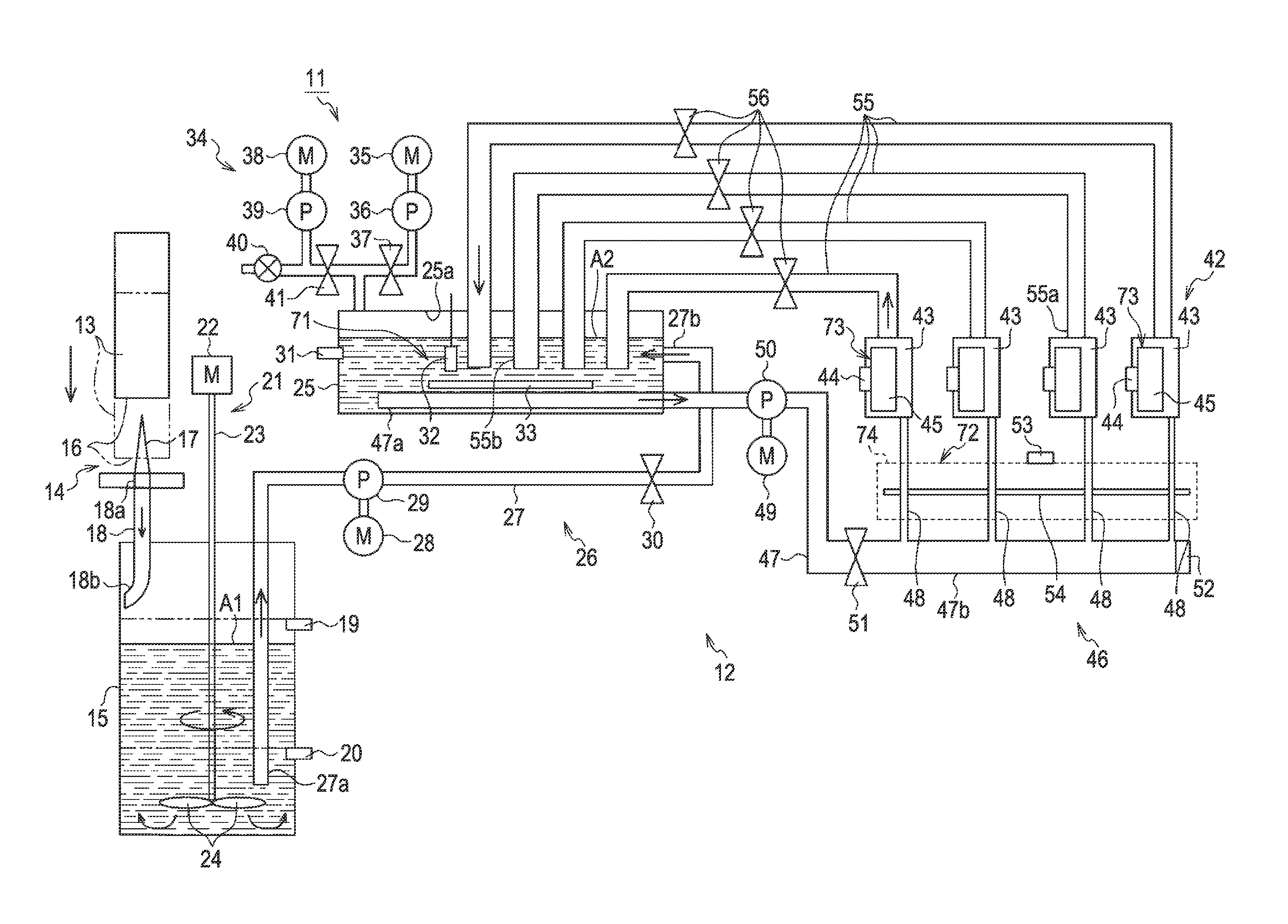
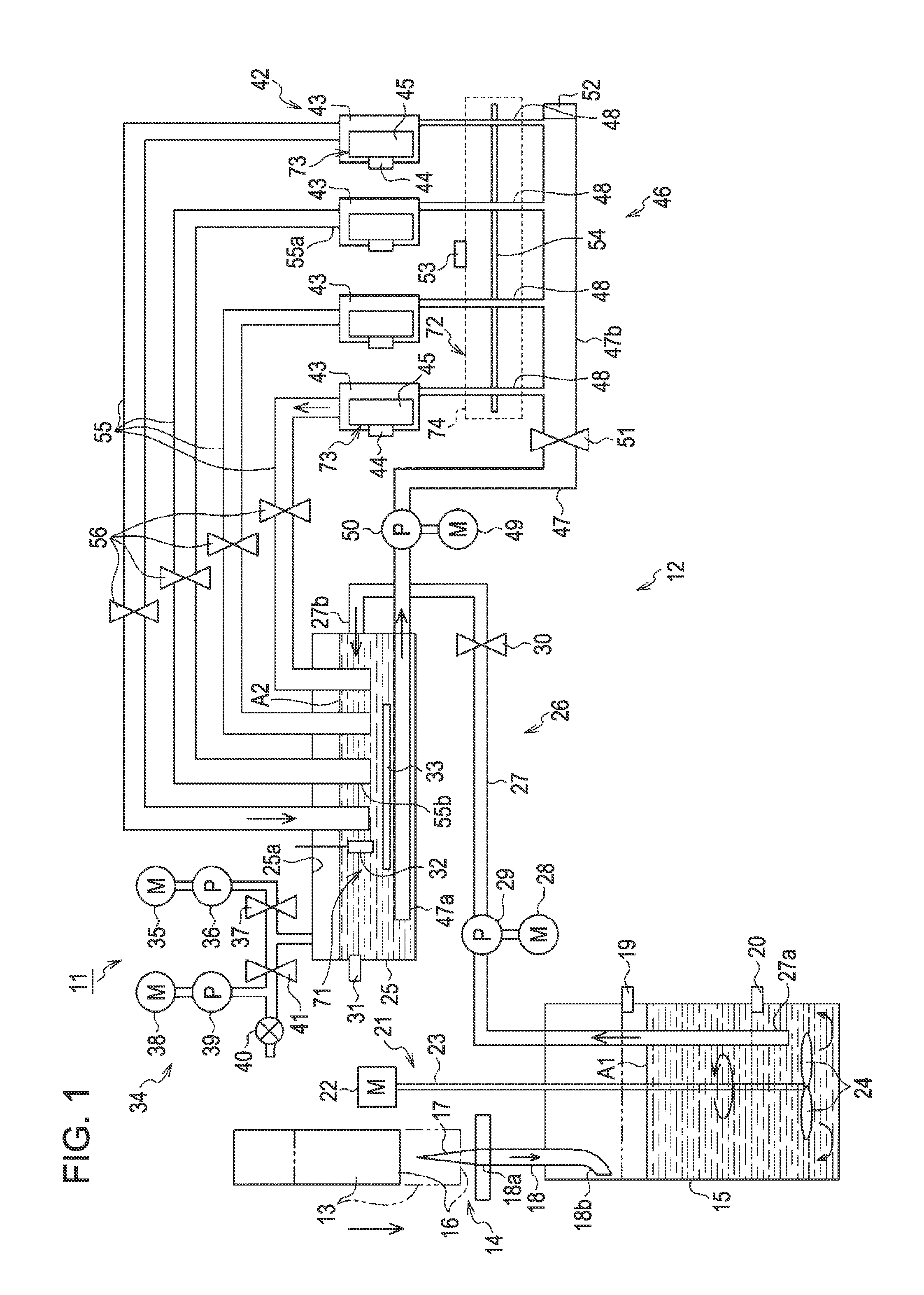
[0037]Hereinafter, an embodiment of the invention will be described with reference to FIG. 1 to FIG. 11.

[0038]As shown in FIG. 1, an ink jet printer (hereinafter, referred to as “printer 11”) as a liquid ejecting apparatus is provided with a printing portion 12 performing a printing process on a target (not shown) (film, etc.) using UV (Ultra Violet) ink (ultra violet curable ink) as an example of a liquid. The printer 11 of the embodiment is provided with an irradiation portion (not shown) irradiating the target printed by the printing portion 12 with an ultraviolet ray to harden the UV ink attached to the target. The UV ink contains a pigment component with low dispersion stability, and has a property that the pigment component is easily precipitated.

[0039]The printing portion 12 is provided with a holder portion 14 on which an ink cartridge 13 storing the UV ink is mounted, and a substantially bottomed cylindrical main tank 15 is disposed under the holder portion 14 in the gravit...


PUM


Abstract

A liquid ejecting apparatus provided with N (N≧2) liquid ejecting heads which eject liquid, the liquid ejecting apparatus including a supply path through which liquid is supplied from a tank to the N liquid ejecting heads, a circulation path through which liquid is returned from the liquid ejecting heads to the tank, N opening and closing valves that are installed for each liquid ejecting head on at least one of the supply path and the circulation path, and a liquid sending unit that applies a force sending the liquid from the tank toward the liquid ejecting heads. M opening and closing valves corresponding to M (M<N) liquid ejecting heads selected as cleaning targets are selected to be opened among the N opening and closing valves and the liquid sending unit is driven, to selectively send liquid to the M liquid ejecting heads of the cleaning targets among the N liquid ejecting heads, thereby performing cleaning.

Description

CROSS-REFERENCE TO RELATED APPLICATION[0001]Japanese Patent Application No. 2009-200906 is hereby incorporated by reference in its entirety.BACKGROUND[0002]1. Field of Invention[0003]The present invention relates to a liquid ejecting apparatus in which a liquid ejecting head ejecting a liquid such as ink performs cleaning and a method of cleaning the liquid ejecting head of the liquid ejecting apparatus.[0004]2. Description of Related Art[0005]As such a liquid ejecting apparatus, for example, an ink jet printer (hereinafter, referred to as “printer”) is described in JP-A-11-342634. The printer described in JP-A-11-342634 is provided with a plurality of head units (printing head) as a liquid ejecting head that ejects ink as a liquid onto a target such as a printing sheet, and ink tanks and sub-tanks that accommodate ink supplied into the head units. At the time of a purge operation of removing bubbles and solids in the ink from the head unit, the ink tank is pressurized by driving an...

Claims


Application Information

Patent Timeline
IPC IPC(8): B41J2/165B41J2/175
CPCB41J2/175B41J2/17596B41J2/17509B41J29/38B41J2/125B41J2/17566B41J2/16526
Inventor KOIKE, KAORUKUMAGAI, TOSHIOYOSHIMOTO, TADAYUKI
Owner SEIKO EPSON CORP
Features
  • Generate Ideas
  • Intellectual Property
  • Life Sciences
  • Materials
  • Tech Scout
  • Unparalleled Data Quality
  • Higher Quality Content
  • 60% Fewer Hallucinations
Learn More