
Liquid crystal display device

a liquid crystal display and display panel technology, applied in non-linear optics, instruments, optics, etc., can solve the problems of uneven display, high possibility, and application of more various kinds of stresses or external forces to the liquid crystal display panel, and achieve the effect of suppressing the occurrence of display unevenness of the liquid crystal display devi

Active Publication Date: 2011-03-03
PANASONIC LIQUID CRYSTAL DISPLAY CO LTD +1
View PDF1 Cites 53 Cited by
  • Summary
  • Abstract
  • Description
  • Claims
  • Application Information

AI Technical Summary

Benefits of technology

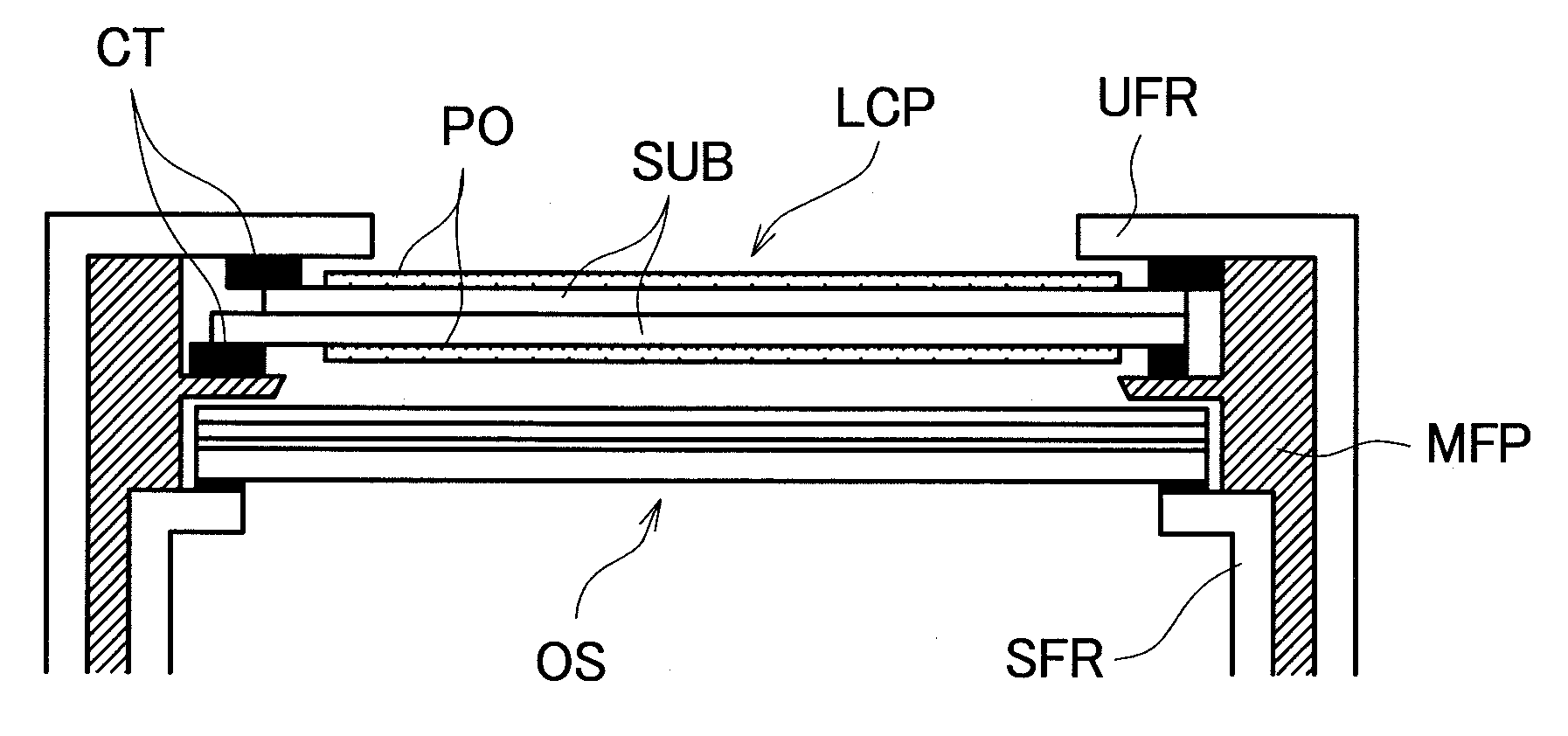
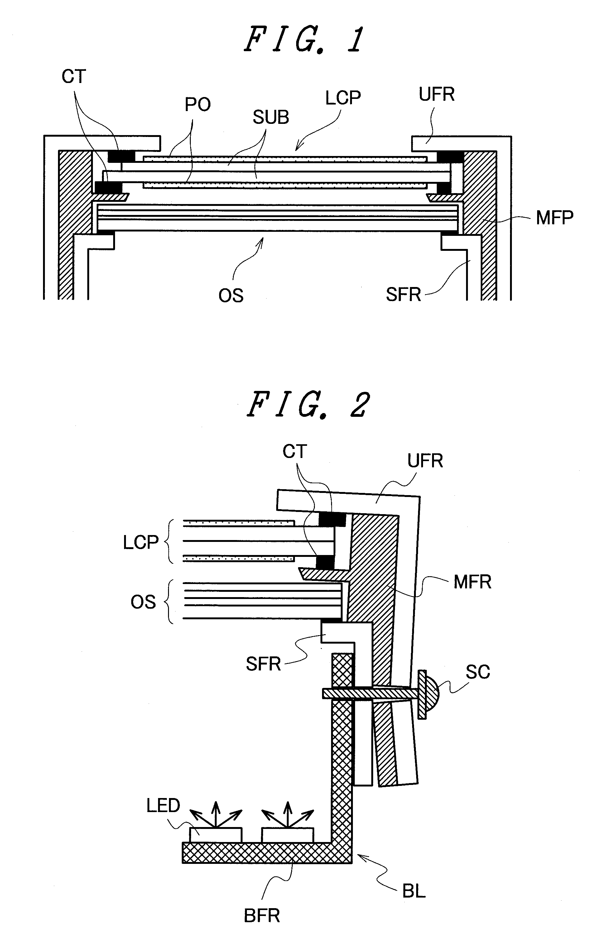
[0010]The liquid crystal display panel LCP is sandwiched between the upper frame UFR and the mold frame MFR. The optical sheet OS is sandwiched between the mold frame MFR and the lower frame SFR. For preventing excessive stress from being applied to the liquid crystal display panel or preventing the liquid crystal display panel from being damaged, a cushion tape CT or the like is disposed between the respective frames at the peripheral portion of the liquid crystal display panel. The cushion tape is also disposed for the optical sheet OS between the respective frames if needed.
[0013]For solving the above-described problem, it is an object of the invention to provide a liquid crystal display device in which a liquid crystal display panel and an optical sheet can be reliably held, and the application of excessive stress to the liquid crystal display panel and the like is suppressed when the liquid crystal display device is assembled or the liquid crystal display device is combined with the backlight means to thereby reduce display unevenness.
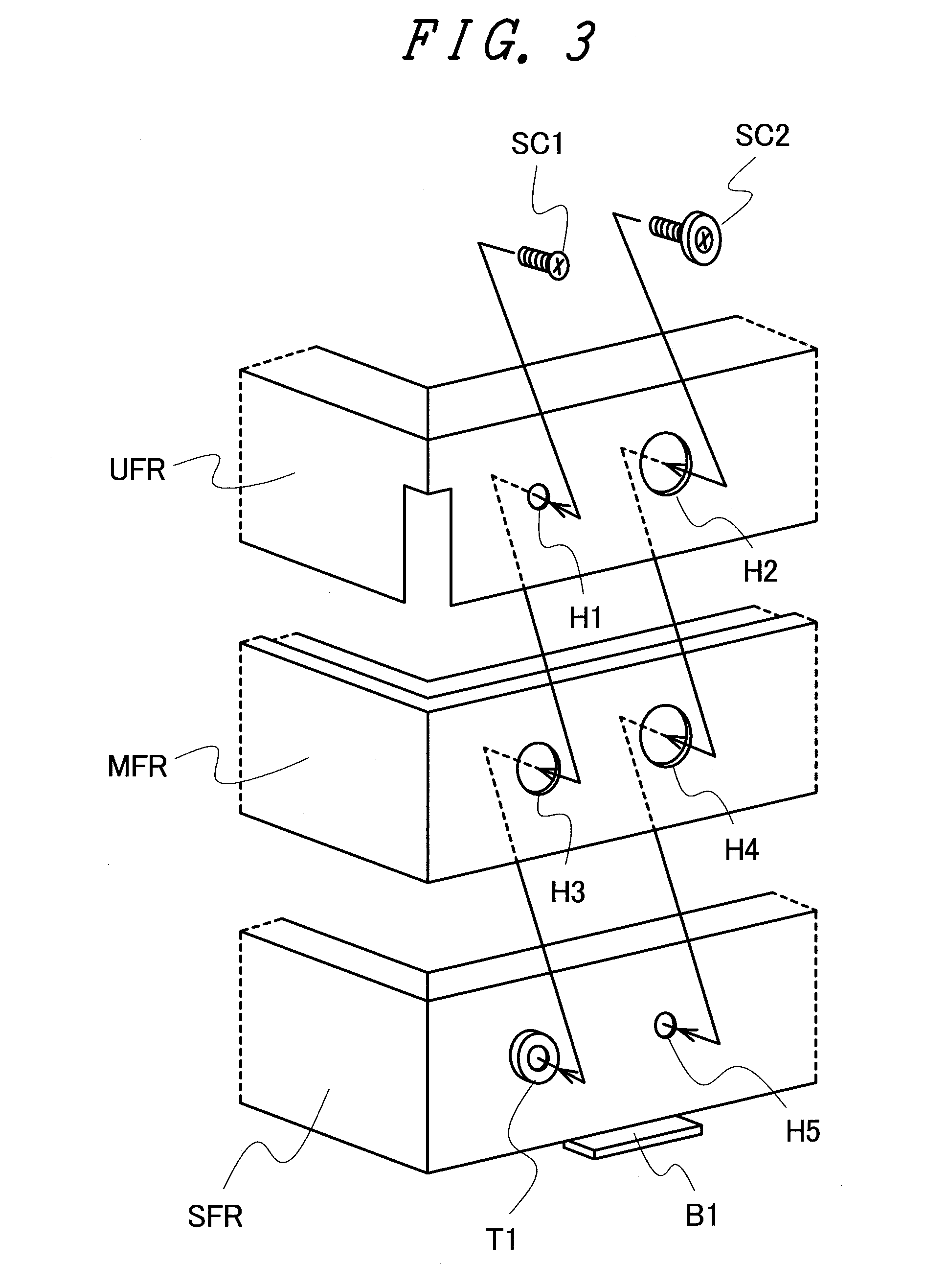
[0024]According to the invention, since the first fixing means for fixing the members constituting the supporting frame of the liquid crystal display device and the second fixing means for fixing the liquid crystal display device to the backlight means are separately disposed, and especially the second fixing means fixedly couples only the lower frame constituting the supporting frame with the backlight means, excessive stress is not applied to the liquid crystal display panel and the like when the liquid crystal display device is assembled or the liquid crystal display device is combined with the backlight means. Therefore, it is possible to suppress the occurrence of display unevenness of the liquid crystal display device.

Problems solved by technology

However, when the liquid crystal display device holding the liquid crystal display panel is combined with the backlight means, excessive stress or external force is applied to the peripheral portion of the liquid crystal display panel, causing the occurrence of display unevenness.
Therefore, when the liquid crystal display device is assembled, or the liquid crystal display device is combined with the backlight means, there is a high possibility that more various kinds of stresses or external forces are applied to the liquid crystal display panel.

Method used


Image

  • Liquid crystal display device
  • Liquid crystal display device
  • Liquid crystal display device

Examples


Embodiment Construction

[0030]A liquid crystal display device according to the invention will be described in detail below. The invention can be suitably used for a liquid crystal display device having a liquid crystal display panel LCP having a liquid crystal layer disposed between substrates SUB facing each other and a supporting frame holding the liquid crystal display panel and capable of being attached and detached to and from backlight means as shown in FIG. 1. Especially when the supporting frame includes a plurality of members, such as an upper frame UFR, a mold frame MFR, and a lower frame SFR, as in the case of including an optical sheet OS disposed on the backlight means side of the liquid crystal display panel LCP, the invention can be more suitably utilized.

[0031]As shown in FIG. 1, the liquid crystal display panel LCP is sandwiched between the upper frame UFR and the mold frame MFR. The optical sheet OS is sandwiched between the mold frame MFR and the lower frame SFR. Further, a cushion tape ...


PUM


Abstract

A liquid crystal display device includes: a liquid crystal display panel having a liquid crystal layer disposed between substrates facing each other; and a supporting frame holding the liquid crystal display panel and capable of being attached to backlight means, wherein an optical sheet disposed on the backlight means side of the liquid crystal display panel is provided, the supporting frame includes an upper frame, a mold frame, and a lower frame, the upper frame and the mold frame sandwiching the liquid crystal display panel therebetween, the mold frame and the lower frame sandwiching the optical sheet therebetween, and first fixing means (including a screw) for fixedly coupling the upper frame, the mold frame, and the lower frame with one another and second fixing means (including a screw) for fixedly coupling only the lower frame with the backlight means are separately disposed.

Description

CROSS-REFERENCE TO RELATED APPLICATION[0001]The present application claims priority from Japanese application JP 2009-193931 filed on Aug. 25, 2009, the content of which is hereby incorporated by reference into this application.BACKGROUND OF THE INVENTION[0002]1. Field of the Invention[0003]The present invention relates to a liquid crystal display device and more particularly to a liquid crystal display device having a supporting frame which holds a liquid crystal display panel and optical sheets and with which the held liquid crystal display panel and the held optical sheets can be attached and detached to and from a backlight which is disposed separately.[0004]2. Description of the Related Art[0005]A liquid crystal display device includes a liquid crystal display panel having a liquid crystal layer disposed between two substrates facing each other and a backlight irradiating the rear surface of the liquid crystal display panel with light. As shown in JP-A-2007-140271 and its corre...

Claims


Application Information

Patent Timeline
IPC IPC(8): G02F1/1333
CPCG02F1/133308G02F1/133608G02F2201/503G02F2001/13332G02F2001/133317G02F1/133317G02F1/13332
Inventor SHIMIZU, SHINJI
Owner PANASONIC LIQUID CRYSTAL DISPLAY CO LTD
Learn More