
Three dimensional display device and method of controlling parallax barrier

a display device and parallax barrier technology, applied in the field of three-dimensional display apparatus, can solve the problem of inability to view three-dimensional images, and achieve the effect of improving viewability and enlarger the viewing distance rang

Active Publication Date: 2011-03-03
SAMSUNG DISPLAY CO LTD
View PDF7 Cites 93 Cited by
  • Summary
  • Abstract
  • Description
  • Claims
  • Application Information

AI Technical Summary

Benefits of technology

The present invention provides a display device and method for displaying images in a three-dimensional format with improved viewability. The device includes a display unit that displays a left eye image and a right eye image by dividing them into a plurality of vertically elongated stripes of images and arranging them alternately in a horizontal direction. A barrier formation unit forms a parallax barrier in front of the display unit, and a distance information acquisition unit obtains the distance between the display unit and the viewer. A slit width control unit controls the slit width of the parallax barrier based on the distance information. The invention also includes a method for controlling the parallax barrier based on the distance between the display unit and the viewer. The technical effects of the invention include improved viewability, enhanced viewer experience, and increased range of viewing distance.

Problems solved by technology

However, in the conventional structure mentioned above, there are problems in that while a visible range of three-dimensional images in a lateral direction can be enlarged, a three-dimensional view is not possible when the distance between the viewer's eyes and the displayed image (such as the LCD panel) deviates from a predetermined preprogrammed distance.

Method used


Image

  • Three dimensional display device and method of controlling parallax barrier
  • Three dimensional display device and method of controlling parallax barrier
  • Three dimensional display device and method of controlling parallax barrier

Examples


Embodiment Construction

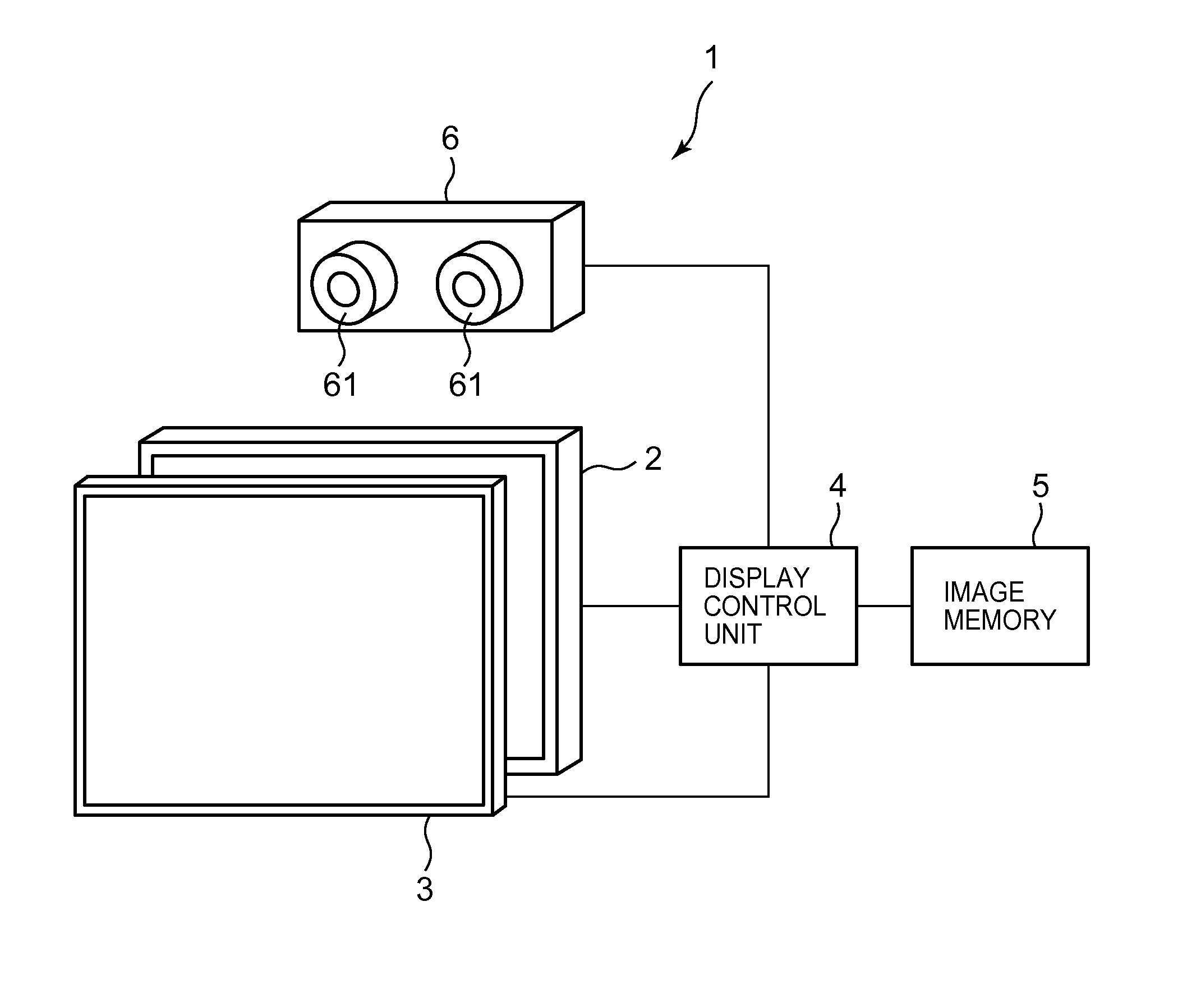
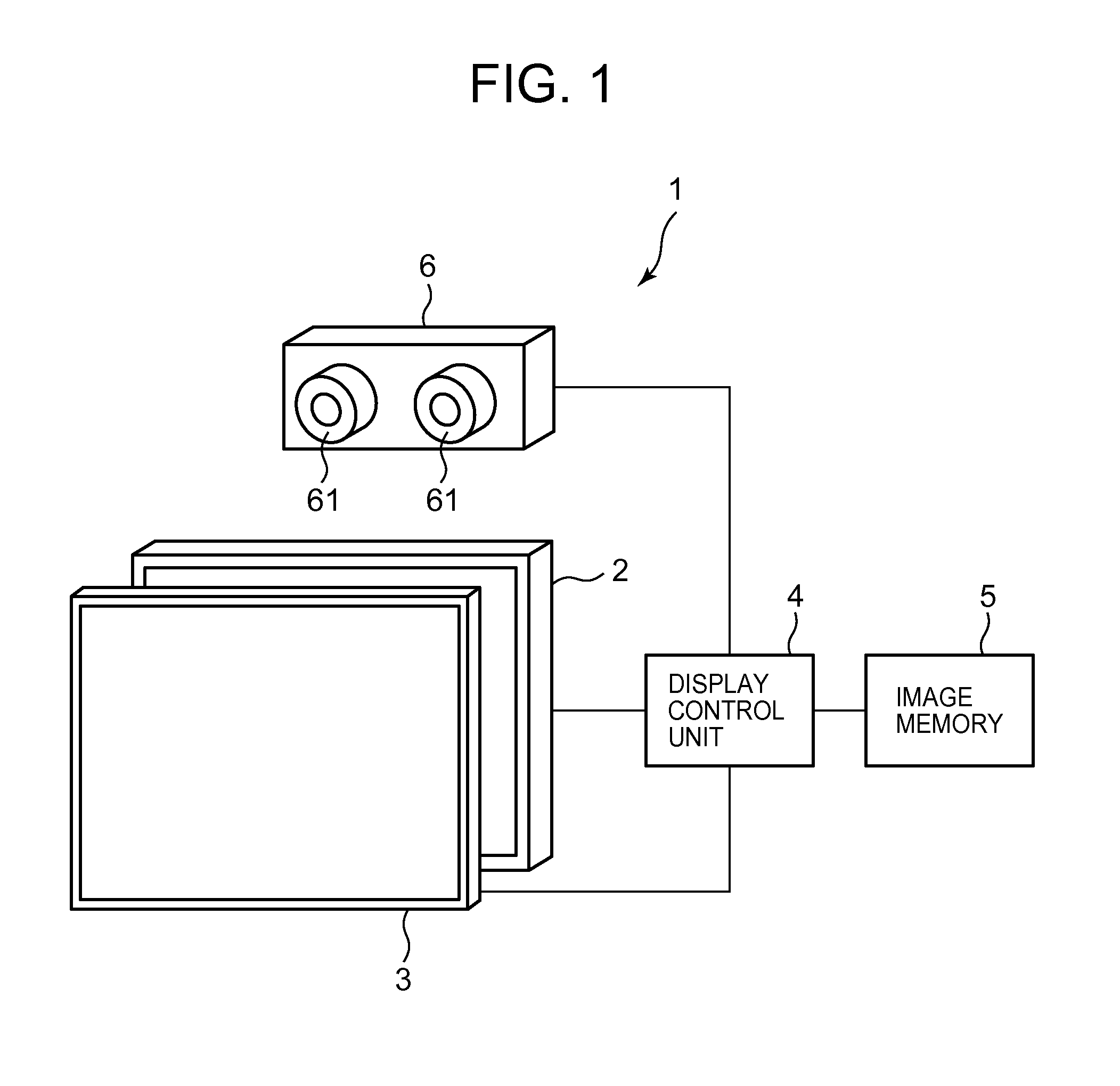
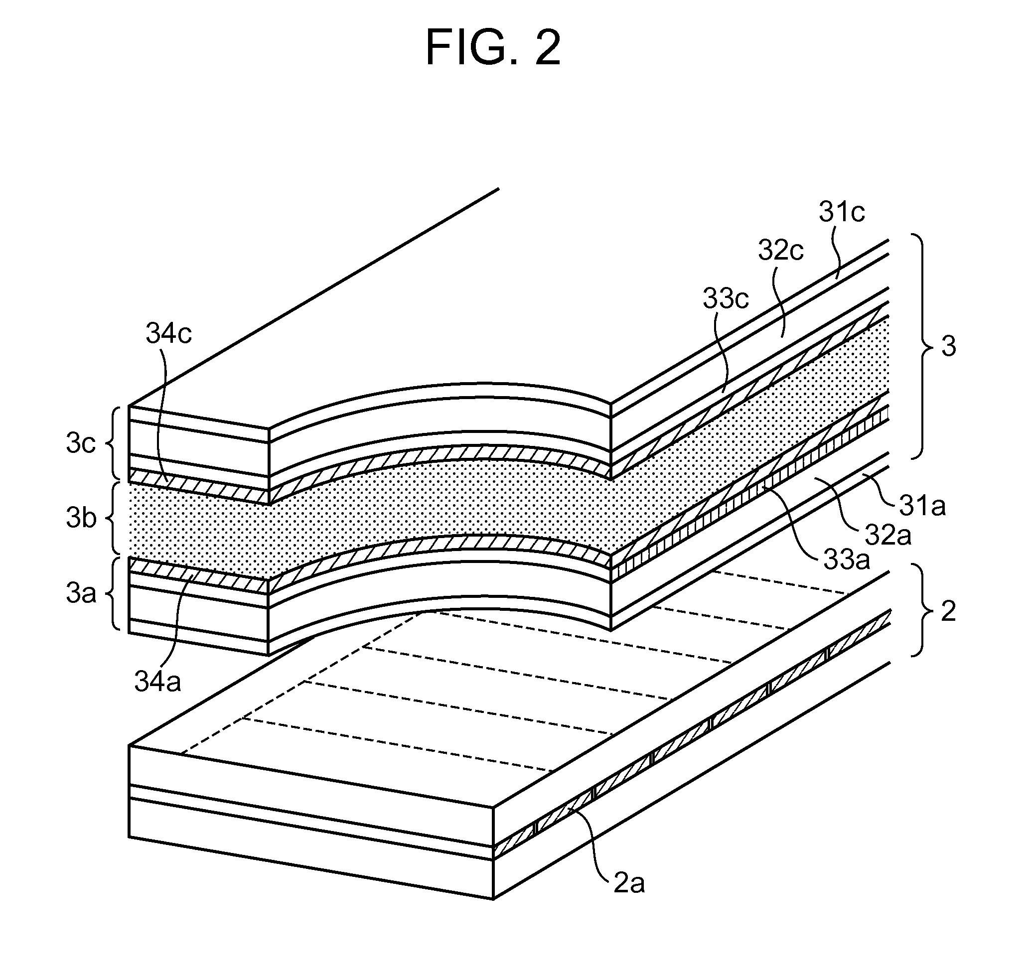
[0042]A preferred embodiment of the present invention is described as follows. FIG. 1 is an illustration showing a schematic configuration of a display device 1 presented as an example of a preferred embodiment of the present invention. The display device 1 realizes a display of a three-dimensional image using a parallax barrier system and, as shown in FIG. 1, includes a display module 2, a barrier control device 3 arranged in front of the display module 2, a display control unit 4, an image memory 5, and a stereo camera unit 6.

[0043]The display module 2 is a display device to display prepared images, such as a normal image, or a pair of a left eye image and a right eye image to be recognized as a three-dimensional image by a viewer, thereby functioning as a display unit of the present embodiment. Here, the word “image” is used synonymously with a word “picture” and indicates still images or moving images. Also, in the following description, the aforementioned normal image is referr...


PUM


Abstract

A three-dimensional display device includes a display unit that displays a left eye image and a right eye image by dividing the images thereof into a plurality of vertically elongated stripes of images and by alternately arranging the divided left eye image and the divided right eye image in a horizontal direction, a barrier formation unit that forms a parallax barrier in front of the display unit, the parallax barrier including a pattern of a plurality of slits to selectively transmit the left eye image and the right eye image towards spatially different points, respectively, that correspond to a left eye and a right eye of the viewer, and a distance measurement unit that measures a distance between the display unit and a viewer viewing the display unit, wherein the barrier formation unit changes the pattern of the slits in the parallax barrier in accordance with the distance measured by the distance measurement unit.

Description

CROSS-REFERENCE TO RELATED APPLICATIONS[0001]This application is based upon and claims the benefit of priority from prior Japanese Patent Application No. 2009-199684, filed Aug. 31, 2009, the entire contents of which are hereby incorporated by reference.BACKGROUND OF THE INVENTION[0002]1. Field of the Invention[0003]The present invention relates to three dimensional display apparatus, and more specifically, to display apparatus and display method for displaying three-dimensional images using a parallax barrier system.[0004]2. Description of the Related Art[0005]Conventionally, a parallax barrier system has been known as a method for achieving a display of three-dimensional images without using special glasses. A display device using a parallax barrier system mainly includes a display device that displays a left eye image and a right eye image alternately every each vertical line, and a parallax barrier that is placed in front of the display device that selectively shades light emitt...

Claims


Application Information

Patent Timeline
Patent Type & Authority Applications(United States)
IPC IPC(8): G02B27/22G02B30/31
CPCG02B27/0093H04N13/0475H04N13/0413G02B27/2214H04N13/315H04N13/373G02B30/31G02F1/1335G02B30/27
Inventor DAIKU, YASUHIRO
Owner SAMSUNG DISPLAY CO LTD
Learn More