Adaptive margin and band control

a technology of adaptive margin and band control, applied in the direction of cross-talk reduction, data switching network, line-transmission details, etc., can solve the problems of affecting the accuracy of data transmitted by dsl and other communication systems, reducing/avoiding/repairing techniques that have performance costs for the communication system in which they are used, and inadequate power transmission levels

Active Publication Date: 2011-03-03
ASSIA SPE LLC CO THE CORP TRUST CO
View PDF53 Cites 45 Cited by
  • Summary
  • Abstract
  • Description
  • Claims
  • Application Information

AI Technical Summary

Benefits of technology

[0014]Configuring or otherwise controlling, parameters of a DSL system related to power, band usage and margin is based on collected operational data. Operational data are collected for at least one DSL system operating under a known configuration and / or a profile. A target profile is selected based on binder-level information. The collected operational data is analyzed and conditions for changing the DSL system configuration to the target profile are evaluated, including any applicable transition rules pertaining to changing profiles. If the conditions hold, then the DSL system is instructed to operate with the target profile. Binder-level information can include deployment point information, topology information, and / or crosstalk coupling information. Collected operational data may include reported modem parameters and / or available modem capabilities such as bit loading procedures, DSL service priorities and others. The controlled parameters may have values that are chosen using one or more spectrum-balancing methods. Such spectrum-balancing methods may be executed infrequently, and may make use of all binder-level information that is available and / or of collected operational data.

Problems solved by technology

Impulse noise, other noise and other sources of error can substantially impact the accuracy of data transmitted by DSL and other communications systems.
These error reduction / avoidance / repair techniques have performance costs for a communication system in which they are used.
As is well known in the art, inadequate power transmission levels lead to errors because the transmission power is not high enough to overcome noise and other interference in a given channel.
Excessively high power transmission levels, however, lead to other problems.
For example, use of transmission power above necessary levels means that the communication system is operated more expensively, to the detriment of all users.
In addition, one or more lines' use of excessive transmission power can generate strong crosstalk problems and interference in nearby lines.
Crosstalk is unwanted interference and / or signal noise electromagnetically passed between lines that share the same or adjacent binders.
FEXT is particularly detrimental in certain loop configurations with different lengths.
In such situations, FEXT from the CO-deployed service may cause considerable degradation to a service deployed from the non-CO location.
Another strong FEXT situation arises with short to medium loop lengths, when a short line can cause strong interference into the receiver of a longer line.
One such situation arises when VDSL service is deployed on loops with different lengths, in which case the FEXT crosstalk interference can be particularly strong in the upstream direction.
NEXT can have a damaging effect in DSL configurations where there is some overlap between the bands used for transmission in the downstream and upstream direction, or where there is signal leakage from a downstream transmitter to an upstream receiver or vice versa.

Method used


Image

  • Adaptive margin and band control
  • Adaptive margin and band control
  • Adaptive margin and band control

Examples


Embodiment Construction

[0031]The following detailed description of the invention will refer to one or more embodiments of the invention, but is not limited to such embodiments. Rather, the detailed description is intended only to be illustrative. Those skilled in the art will readily appreciate that the detailed description given herein with respect to the Figures is provided for explanatory purposes as the invention extends beyond these illustrative embodiments.

[0032]It should be kept in mind that the specifics provided herein are for purposes of illustration and that the present invention is broader than any one example. Therefore, the present invention should be construed as broadly as possible and permitted.

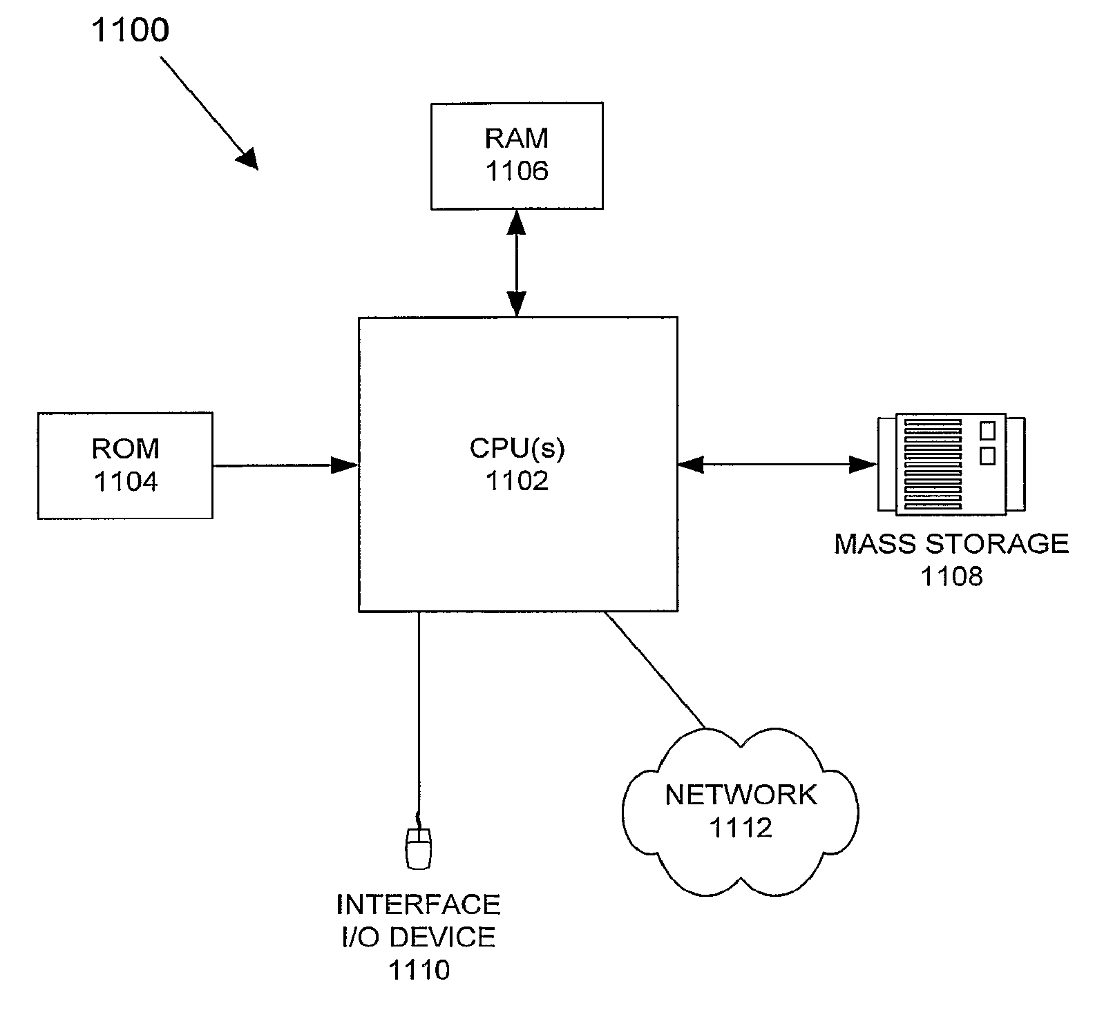
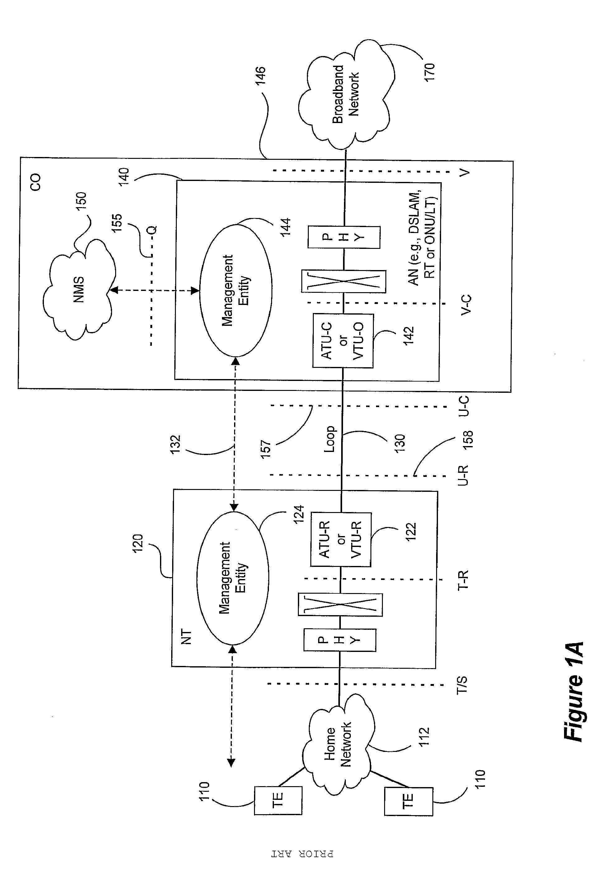
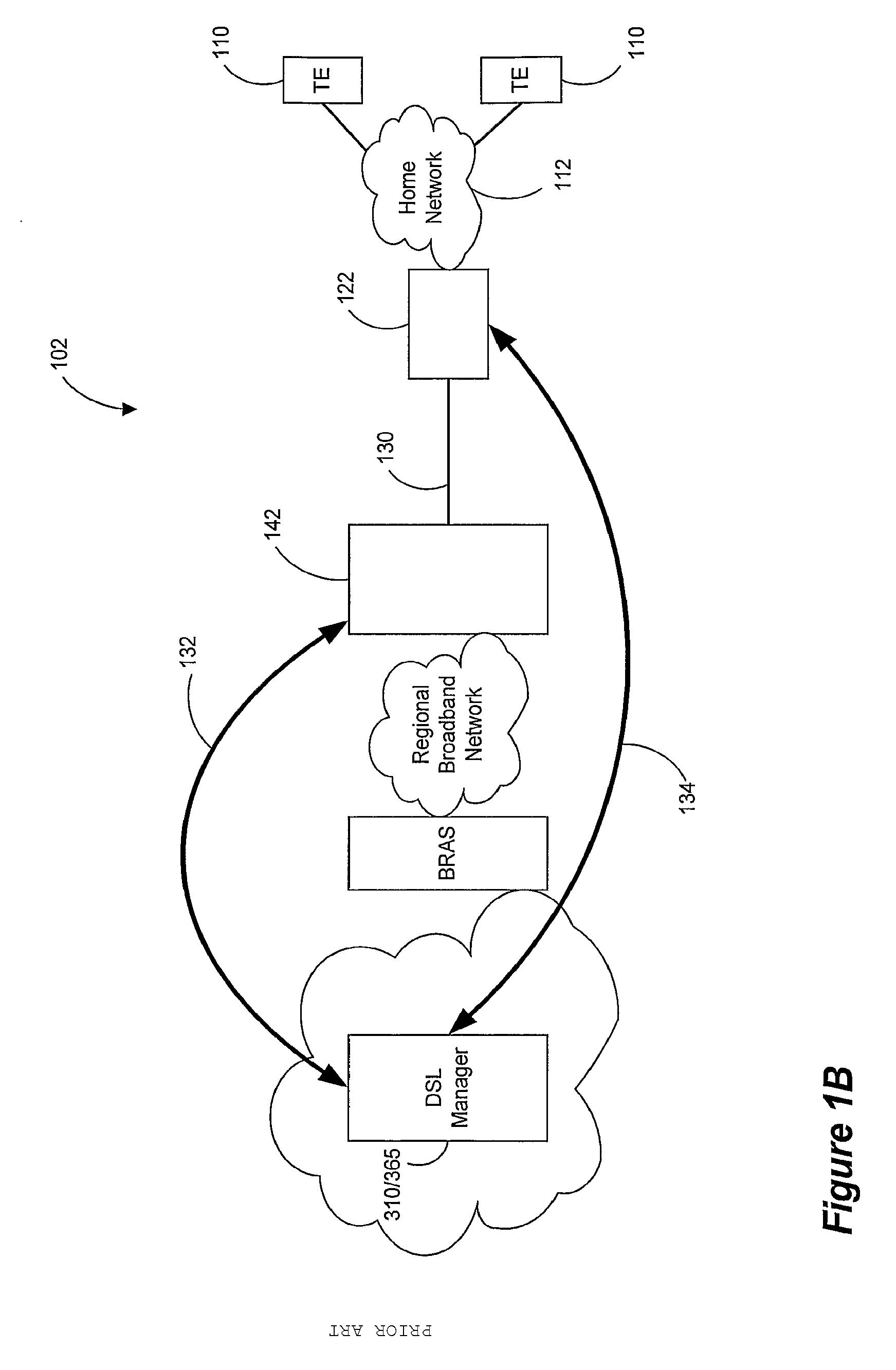
[0033]Generally, embodiments of the present invention will be described in connection with the operation of a Digital Subscriber Line (DSL) system having a controller (for example, a computer system or control processor, which may or may not be embedded into a Digital Subscriber Line Access Multipl...


PUM


Abstract

Configuration or otherwise controlling parameters of a Digital Subscriber Line (DSL) system related to power, band usage and margin is based on collected operational data. Operational data are collected from at least one DSL system operating under a known configuration and/or a profile. A target profile is selected based on binder-level information. The collected operational data is analyzed and conditions for changing the DSL system configuration to the target profile are evaluated, including any applicable transition rules pertaining to changing profiles. If the conditions hold, then the DSL system is instructed to operate with the target profile. Binder-level information can include deployment point information, topology information, and/or crosstalk coupling information. The controlled parameters may have values that are chosen using one or more spectrum balancing methods. Such spectrum balancing methods may be executed infrequently, and may make use of all binder-level information that is available.

Description

CROSS-REFERENCE TO RELATED APPLICATIONS[0001]This application is a continuation-in-part of U.S. patent application Ser. No. 10 / 893,826 filed on Jul. 19, 2004, entitled ADAPTIVE MARGIN AND BAND CONTROL, which claims the benefit of priority under 35 U.S.C. §119(e) of U.S. Provisional Patent Application No. 60 / 527,853 filed on Dec. 7, 2003, entitled DYNAMIC MANAGEMENT OF COMMUNICATION SYSTEM, the disclosures of which are incorporated herein by reference in their entirety for all purposes.[0002]This application is a continuation of U.S. patent application Ser. No. 11 / 995,195 which is a national stage application of PCT / US06 / 26796 filed on Jul. 8, 2006. The PCT / US06 / 26796 application claims the benefit of priority under 35 U.S.C. §119(e) of the following:[0003]U.S. Provisional Patent Application No. 60 / 698,113 filed on Jul. 10, 2005, entitled DSL SYSTEM, the disclosure of which is incorporated herein by reference in its entirety for all purposes; and[0004]U.S. Provisional Patent Applicat...

Claims


Application Information

Patent Timeline
Patent Type & Authority Applications(United States)
IPC IPC(8): H04M3/24
CPCH04B3/32H04M11/062H04L1/0019H04L5/0007H04L5/0037H04L5/0046H04L12/26H04L12/2856H04L12/2874H04L12/2892H04L12/2898H04L12/40013H04L12/6418H04L12/66H04L41/0816H04L41/142H04L43/00H04L43/0829H04L43/0847H04L43/0888H04L43/0894H04L43/106H04L43/16H04L2012/6478H04M3/007H04M3/2209H04M3/304H04L1/0002
Inventor CIOFFI, JOHN M.RHEE, WONJONGGINIS, GEORGIOSCHUNG, SEONG TAEK
Owner ASSIA SPE LLC CO THE CORP TRUST CO
Why Eureka
Try Eureka