Cooling device and image forming device
- Summary
- Abstract
- Description
- Claims
- Application Information
AI Technical Summary
Benefits of technology
Problems solved by technology
Method used
Image
Examples
embodiment 1
[0085]FIGS. 6(a) and 6(b) are diagrams illustrating a configuration according to Embodiment 1 of the present invention. FIG. 6(a) is a lateral view of the heat receiving plate 31 being tucked in and FIG. 6(b) is a lateral view of the heat receiving plate 31 being pulled out. Moreover, in FIGS. 6(a) and 6(b), the fixing device 8, etc. are omitted.
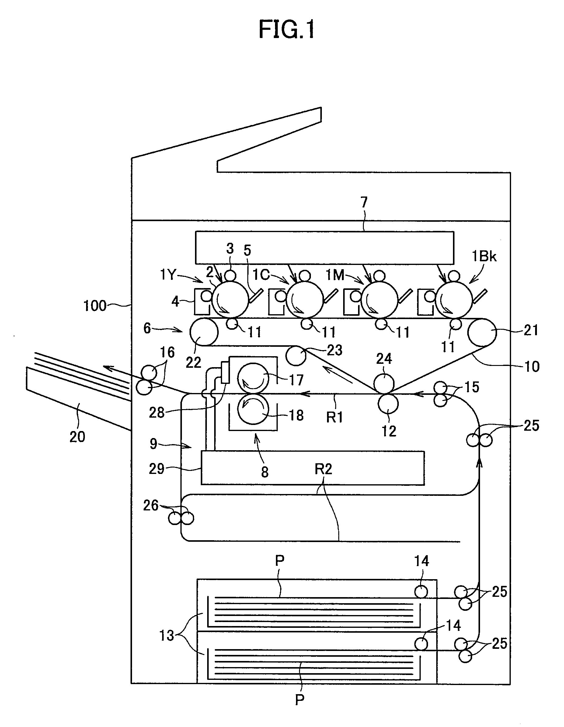
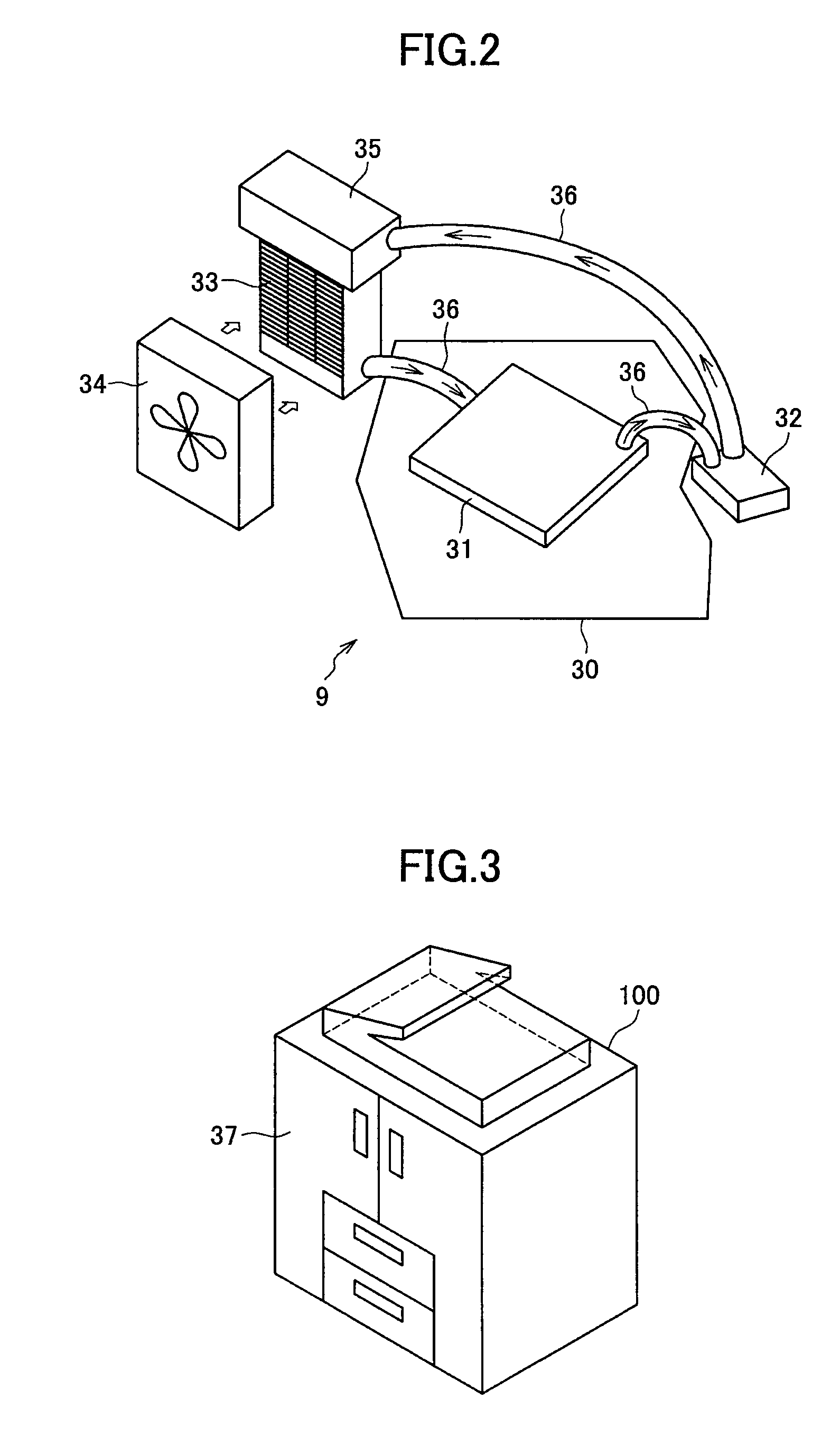
[0086]As illustrated in FIGS. 6(a) and 6(b), a supply tube 40 for supplying the cooling liquid into the heat receiving plate 31 and a discharge tube 41 for discharging the cooling liquid from the heat receiving plate 31 are connected to the heat receiving plate 31. The supply tube 40 and the discharge tube 41 are flow channels which make up a part of the circulation routes 36 as shown in FIG. 2. More specifically, a connecting member which connects the heat receiving plate 31 and the radiator 33 is the supply tube 40, while a connecting member which connects the heat receiving plate 31 and the pump 32 is the discharge tube 41. The supply tub...
embodiment 2
[0091]FIG. 7 is a diagram illustrating a configuration according to Embodiment 2 of the present invention with a lateral view of the heat receiving plate 31 being pulled out.
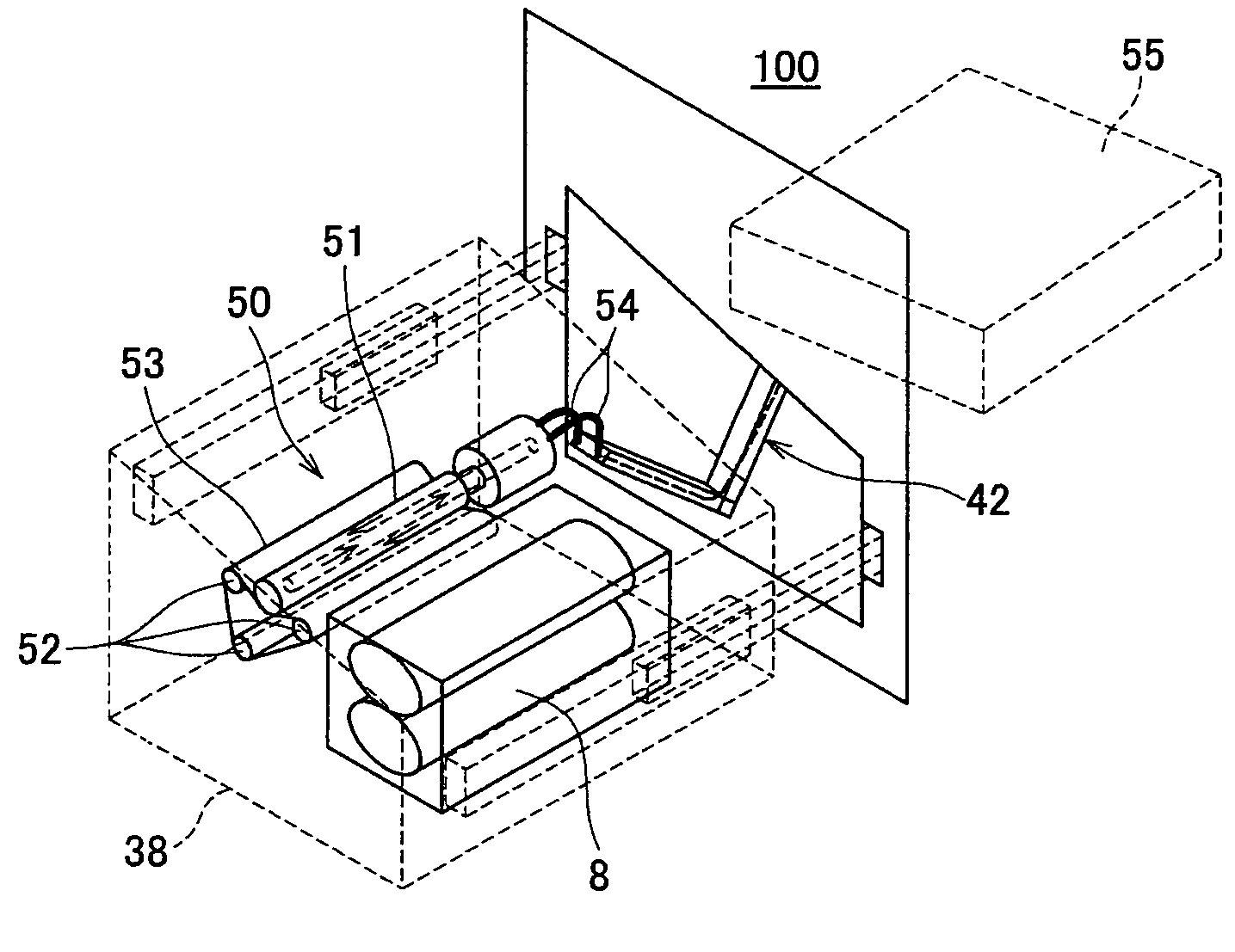
[0092]As shown in FIG. 7, in Embodiment 2, in a manner similar to Embodiment 1, an extending / contracting supporting unit 42 is provided which includes multiple arm members 42b oscillatably connected via the joint section 42a, the supply tube 40 and the discharge tube 41 being tucked in the arm members 42b. Moreover, in Embodiment 2, a joint section 42a of the extending / contracting supporting unit 42 is mounted to the sliding member 39 which supports the pulling out section 38 in such a manner that the pulling out section 38 can be pulled out and tucked in. More specifically, a joint section 42a which is arranged on the upper side out of multiple joint sections 42a alternately arranged in the upward and downward directions is mounted to the sliding member 39. In this way, the extending / contracting supporting unit...
embodiment 3
[0095]FIGS. 8 and 9 are diagrams illustrating configurations according to Embodiment 3 of the present invention. FIG. 8 is a lateral view of the heat receiving plate 31 being pulled out, while FIG. 9 is a top view of the heat receiving plate 31 being pulled out. In FIGS. 8 and 9, the fixing device 8, which is provided at the pulling out section 38, is omitted.
[0096]As shown in FIG. 8 or FIG. 9, in Embodiment 3, as in Embodiment 1, there is provided an extending / contracting supporting unit 42 which includes multiple arm members 42b, which are oscillatably connected via the joint section 42a. Moreover, as shown in FIG. 9, the supply tube 40 and the discharge tube 41 are carried within the arm member 42b. In Embodiment 3, unlike the previously-described Embodiments, the arm members 42b are arranged such that they bend laterally in a zigzag manner. Moreover, the arm member 42b is arranged such that it contacts a bottom plate 43 which is arranged at the image forming device body 100. In ...
PUM
 Abstract
Description
Claims
Application Information
 - R&D
- Intellectual Property
- Life Sciences
- Materials
- Tech Scout
- Unparalleled Data Quality
- Higher Quality Content
- 60% Fewer Hallucinations
Browse by: Latest US Patents, China's latest patents, Technical Efficacy Thesaurus, Application Domain, Technology Topic, Popular Technical Reports.
© 2025 PatSnap. All rights reserved.Legal|Privacy policy|Modern Slavery Act Transparency Statement|Sitemap|About US| Contact US: help@patsnap.com


