
Remote Vehicle

Active Publication Date: 2011-03-03
FLIR DETECTION
View PDF4 Cites 44 Cited by
  • Summary
  • Abstract
  • Description
  • Claims
  • Application Information

AI Technical Summary

Benefits of technology

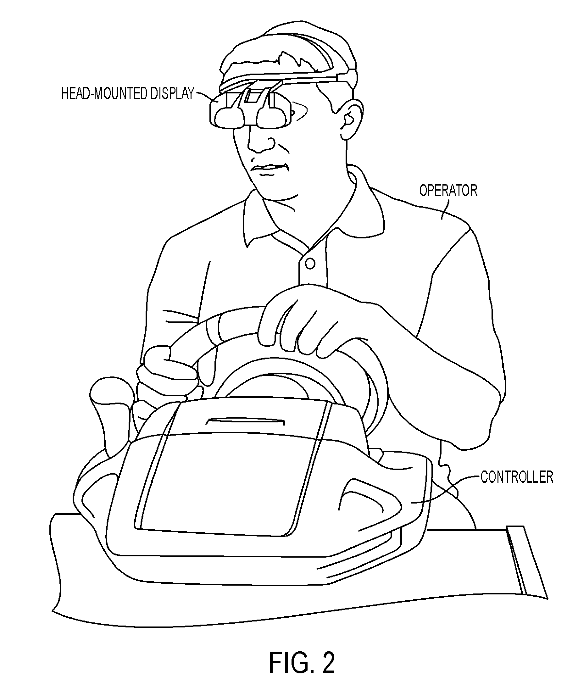
[0008]The present teachings also provide a system for providing enhanced operator control of a remote vehicle driving at increased speeds. The system comprises: a head-mounted display configured to be worn by the operator and track a position of the operator's head; a head-aimed camera mounted to the remote vehicle via a pan / tilt mechanism and configured to pan and tilt in accordance with the position of the operator's head, the head-aimed camera transmitting video to be displayed to the operator via the head-mounted display; and a computer running a behavior engine, the computer receiving input from the operator and one or more sensors, and being configured to utilize the behavior engine, operator input, sensor input, and one or more autonomous and / or semi-autonomous behaviors to assist the operator in driving the remote vehicle.

Problems solved by technology

Existing small unmanned ground vehicles (UGVs) are presently limited to speeds of less than about 6 mph.
Such limited speed capabilities can be undesirable when the UGV must be driven a long distance to a target or when time is of the essence in an operation.
Further, existing UGV implementations may be difficult to control at high speeds.
In addition, a bump that would typically be absorbed by a large vehicle's suspension can send a small, fast-moving UGV flying into the air.
In certain instances, the cleated (high traction) tracks currently used on many small UGVs drain a great deal of power when trying to operate the UGV at increased speeds.
When a vehicle oversteers, its rear tires lose traction before the front tires, which can cause the vehicle to turn more than commanded.
Vehicles with more weight on the rear wheels tend to oversteer more easily.
Vehicles with more weight on the front wheels tend to understeer more easily.
Understeer is almost always undesirable, whereas skilled drivers can utilize oversteer to take turns faster than otherwise possible.

Method used


Image

  • Remote Vehicle
  • Remote Vehicle
  • Remote Vehicle

Examples


Embodiment Construction

[0019]Reference will now be made in detail to exemplary embodiments of the present teachings, examples of which are illustrated in the accompanying drawings.

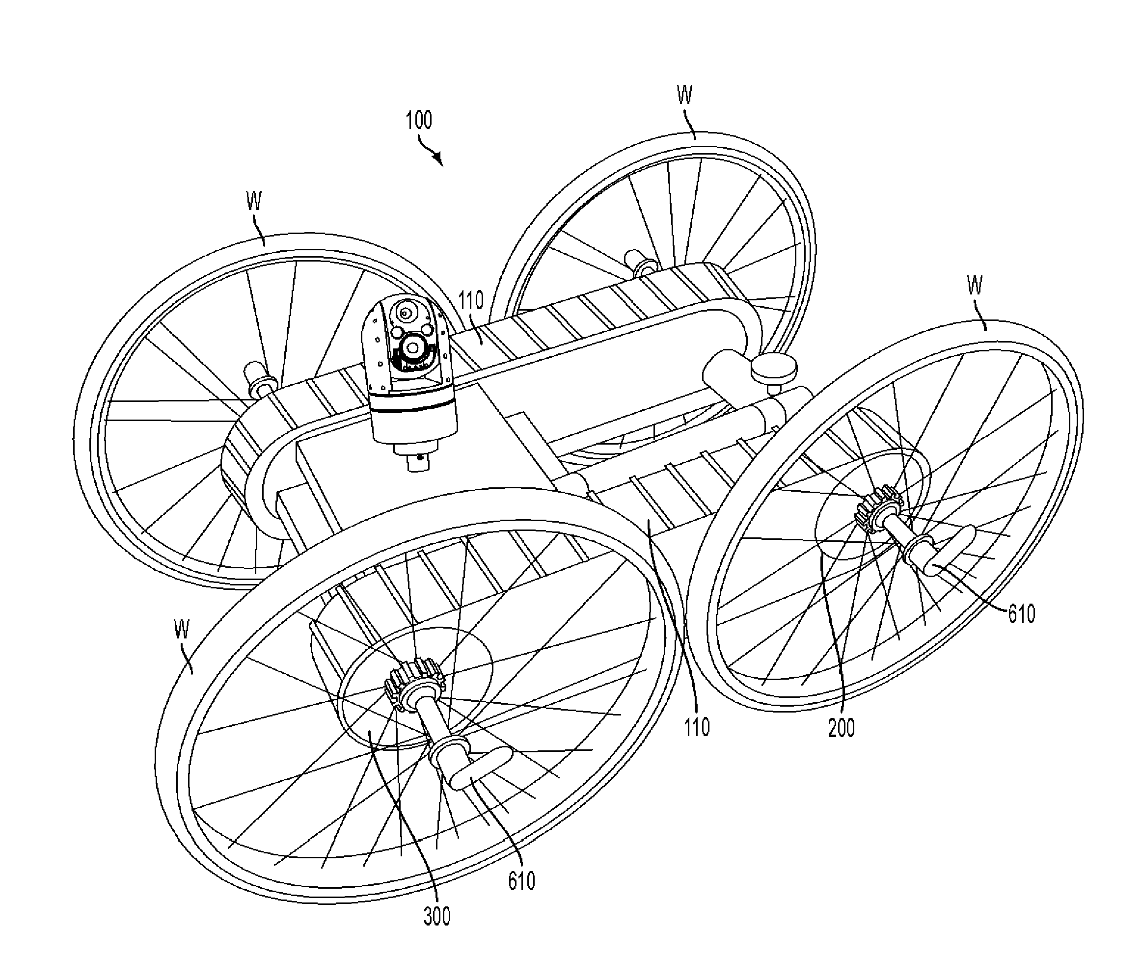
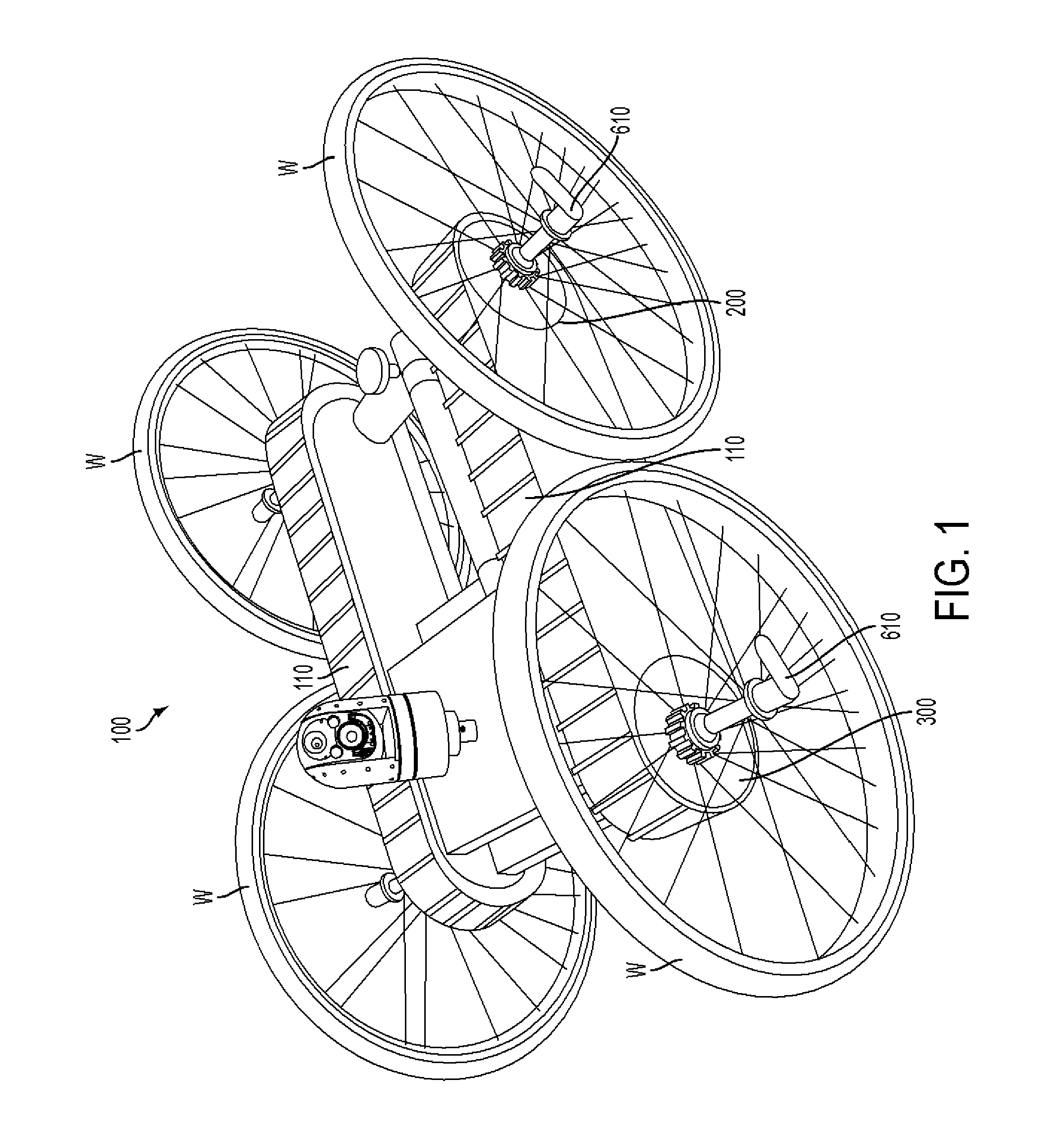
[0020]The present teachings provide a remote vehicle capable of increased speed, and combine immersive telepresence (for increasing an operator's situational awareness in his own environment and / or in an environment of a remote vehicle) with semi-autonomous driver-assisted behaviors (for reducing an operator's cognitive load when maintaining situational awareness while controlling a remote vehicle at higher speeds) that command the remote vehicle to safely maneuver according to the driver's intent. A remote vehicle, such as an iRobot® PackBot® or Warrior™ 700 (described in more detail below), portions of the chassis of which are illustrated in FIG. 1, can be modified as described below for high-speed operation.

[0021]Immersive telepresence can be achieved for use in accordance with certain embodiments of the present teachings by ...


PUM


Abstract

A system for providing enhanced operator control of a remote vehicle driving at increased speeds comprises: a head-mounted display configured to be worn by the operator and track a position of the operator's head; a head-aimed camera mounted to the remote vehicle via a pan / tilt mechanism and configured to pan and tilt in accordance with the position of the operator's head, the head-aimed camera transmitting video to be displayed to the operator via the head-mounted display; and a computer running a behavior engine, the computer receiving input from the operator and one or more sensors, and being configured to utilize the behavior engine, operator input, sensor input, and one or more autonomous and / or semi-autonomous behaviors to assist the operator in driving the remote vehicle. The remote vehicle includes releasably mounted wheels and high-friction tracks.

Description

INTRODUCTION[0001]The invention described herein may be manufactured and used by, or for the Government of the United States for governmental purposes without the payment of any royalties thereon.[0002]The present teachings provide a remote vehicle with increased speed capabilities. Various embodiments of the present teachings can provide a remote vehicle with selectively increased speed capabilities or temporarily increased speed capabilities.BACKGROUND [0003]Existing small unmanned ground vehicles (UGVs) are presently limited to speeds of less than about 6 mph. Such limited speed capabilities can be undesirable when the UGV must be driven a long distance to a target or when time is of the essence in an operation. Further, existing UGV implementations may be difficult to control at high speeds. For example, existing small UGVs need to steer around obstacles that larger vehicles could simply driver over. In addition, a bump that would typically be absorbed by a large vehicle's suspe...

Claims


Application Information

Patent Timeline
IPC IPC(8): G05D1/02B60K17/342G06F19/00
CPCB60K17/342G05D2201/0207G05D1/0038
Inventor YAMAUCHI, BRIAN MASAOMASSEY, KENT CONWAYLAFFERTY, DAVID AARON
Owner FLIR DETECTION
Learn More