Laminated gas sensor element, gas sensor equipped with laminated gas sensor element, and method for manufacturing laminated gas sensor element

a gas sensor and laminate technology, applied in the direction of instruments, coatings, measurement devices, etc., can solve the problems of large pores not being able to absorb thermal shrinkage of cracks or fissures are apt to generate in the porous protection layer, and the layer deterioration, so as to achieve reliable restraining the generation

Active Publication Date: 2011-03-10
NGK SPARK PLUG CO LTD
View PDF5 Cites 3 Cited by
  • Summary
  • Abstract
  • Description
  • Claims
  • Application Information

AI Technical Summary

Benefits of technology

[0008]It is therefore an object of the present invention to provide a technique for more reliably restraining the generation of a crack in a gas sensor element which could otherwise result from adhesion of water.

Problems solved by technology

Specifically, in the case where the number of large pores within an area measuring 100 μm×100 μm is less than one, the large pores fail to absorb thermal shrinkage of the porous protection layer.
As a result, a crack or fissure is apt to generate in the porous protection layer.
In the case where the number of large pores within an area measuring 100 μm×100 μm is 20 or more, the strength of the porous protection layer deteriorates, or water droplets and the like are apt to reach the gas sensor element through the large pores, resulting in deterioration in resistance to water adhesion.

Method used


Image

  • Laminated gas sensor element, gas sensor equipped with laminated gas sensor element, and method for manufacturing laminated gas sensor element
  • Laminated gas sensor element, gas sensor equipped with laminated gas sensor element, and method for manufacturing laminated gas sensor element
  • Laminated gas sensor element, gas sensor equipped with laminated gas sensor element, and method for manufacturing laminated gas sensor element

Examples


Embodiment Construction

[0116]An embodiment of the present invention will next be described in the following sequence and with reference to the drawings. However, the present invention should not be construed as being limited thereto.[0117]A. Configuration of gas sensor[0118]B. Configuration of gas sensor element[0119]C. Porous protection layer on distal end portion of gas sensor element[0120]D. Method for manufacturing porous protection layer[0121]E. Water adhesion resistance test[0122]F. Modifications

A. Configuration of Gas Sensor:

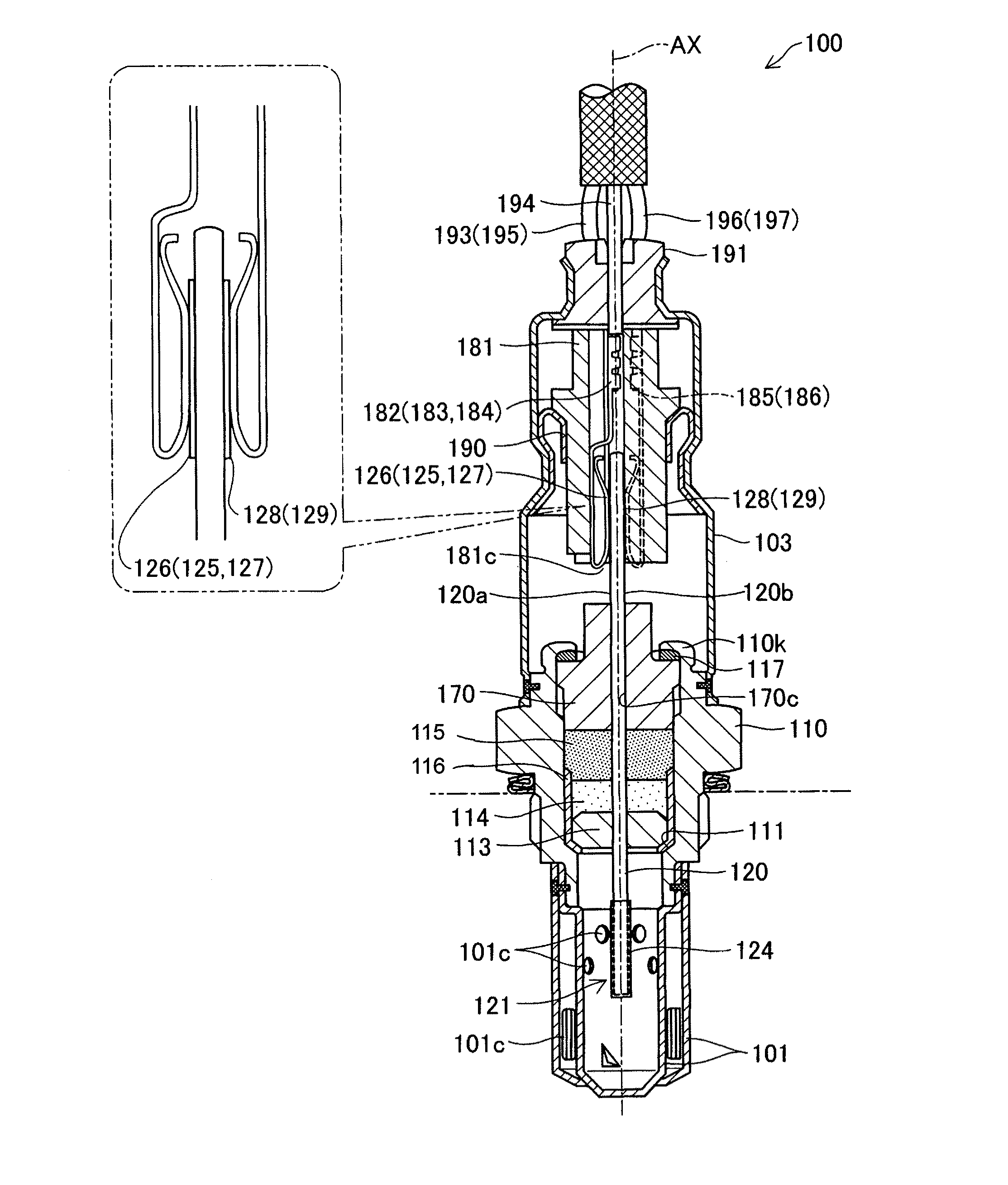
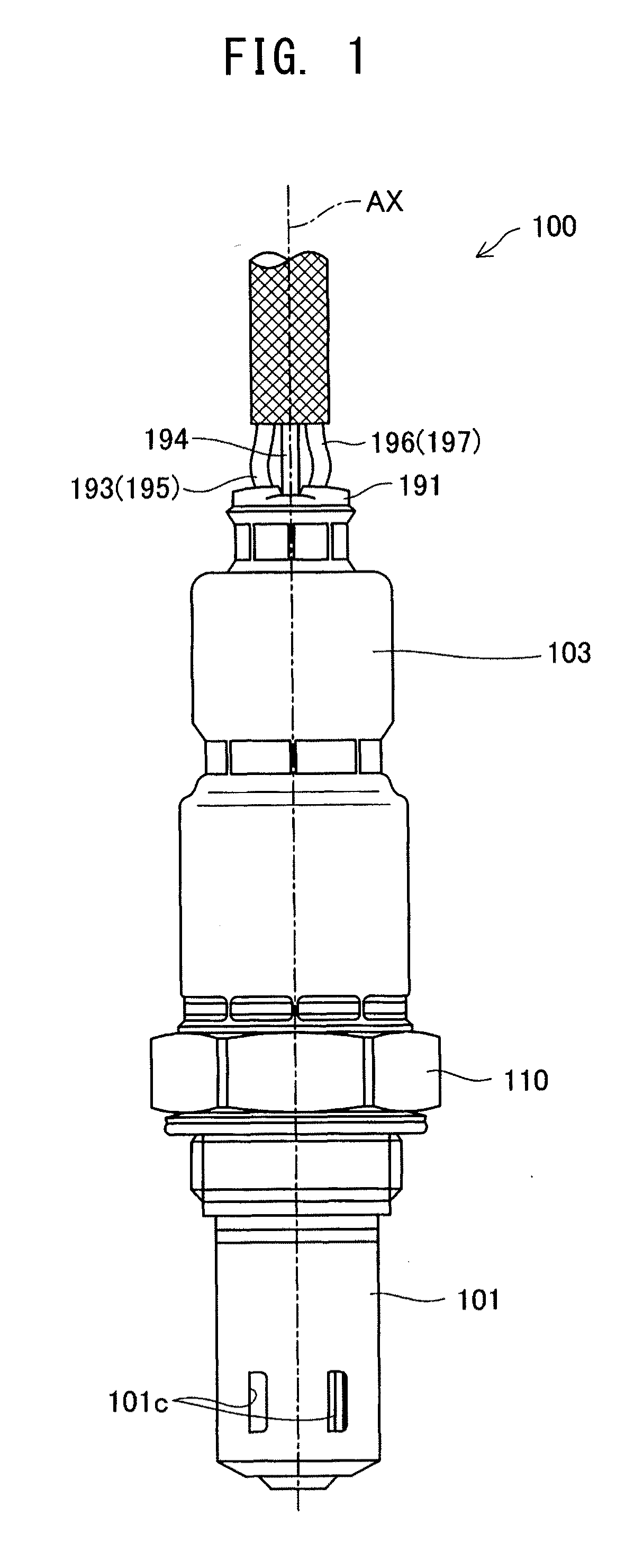
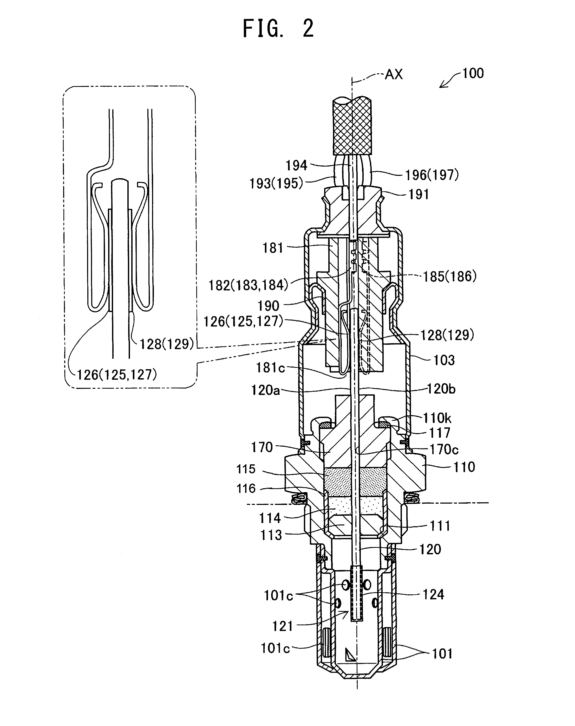
[0123]FIG. 1 is an external view of a gas sensor 100 according to an embodiment of the present invention. FIG. 2 is a sectional view of the gas sensor 100. In FIGS. 1 and 2, the lower side corresponds to a distal side with respect to a direction of axis AX, and the upper side corresponds to a proximal side with respect to the direction of axis AX. The gas sensor 100 is a full range air / fuel ratio sensor attached to an exhaust pipe of an internal combustion engine, and is adapte...


PUM

PropertyMeasurementUnit
diameteraaaaaaaaaa
diameteraaaaaaaaaa
diameteraaaaaaaaaa

Abstract

A laminated gas sensor element including a detection element including a solid electrolyte body having a pair of electrodes formed thereon laminated together with a heater element. A porous protection layer is formed on at least a distal end portion of the laminated gas sensor element which is to be exposed to a gas to be measured. The surface of the porous protection layer has 10 or more small pores each having a diameter of 1 μm to 5 μm inclusive and an aspect ratio of 0.5 to 2.0 inclusive within an area measuring 50 μm×50 μm, and one to less than 20 large pores each having a diameter of 8 μm to 20 μm inclusive and an aspect ratio of 0.5 to 2.0 inclusive within an area measuring 100 μm×100 μm. Also disclosed is a method for manufacturing the laminated gas sensor.

Description

BACKGROUND OF THE INVENTION[0001]1. Field of the Invention[0002]The present invention relates to a laminated gas sensor element, a gas sensor equipped with the laminated gas sensor element, and a method for manufacturing the laminated gas sensor element.[0003]2. Description of the Related Art[0004]Conventionally, known gas sensors include those for detecting a particular gas component contained in exhaust gas or for measuring the concentration of the particular gas component. Some of these gas sensors employ a laminated gas sensor element configured such that a pair of electrodes are provided on a solid electrolyte body. The solid electrolyte body of zirconia or the like used in the gas sensor element becomes active at a high temperature of 300° C. or higher. Usually, the gas sensor element is used in an activated state upon heating by a heater laminated on the solid electrolyte body. In this case, adhesion, to the gas sensor element, of a water or oil droplet contained in a gas to ...

Claims


Application Information

Patent Timeline
Patent Type & Authority Applications(United States)
IPC IPC(8): G01N27/407B05D5/12
CPCG01N27/4071
Inventor MURAOKA, TATSUHIKOMIZUTANI, MASAKI
Owner NGK SPARK PLUG CO LTD
Why Eureka
Try Eureka