Injector

Active Publication Date: 2011-03-10
DENSO CORP
View PDF11 Cites 35 Cited by
  • Summary
  • Abstract
  • Description
  • Claims
  • Application Information

AI Technical Summary

Problems solved by technology

In addition, because of wear caused between the inclined moving core 1 and a housing 5

Method used


Image

  • Injector
  • Injector
  • Injector

Examples


first embodiment

[0035]A first embodiment of the invention will be described below with reference to FIGS. 1 to 3.

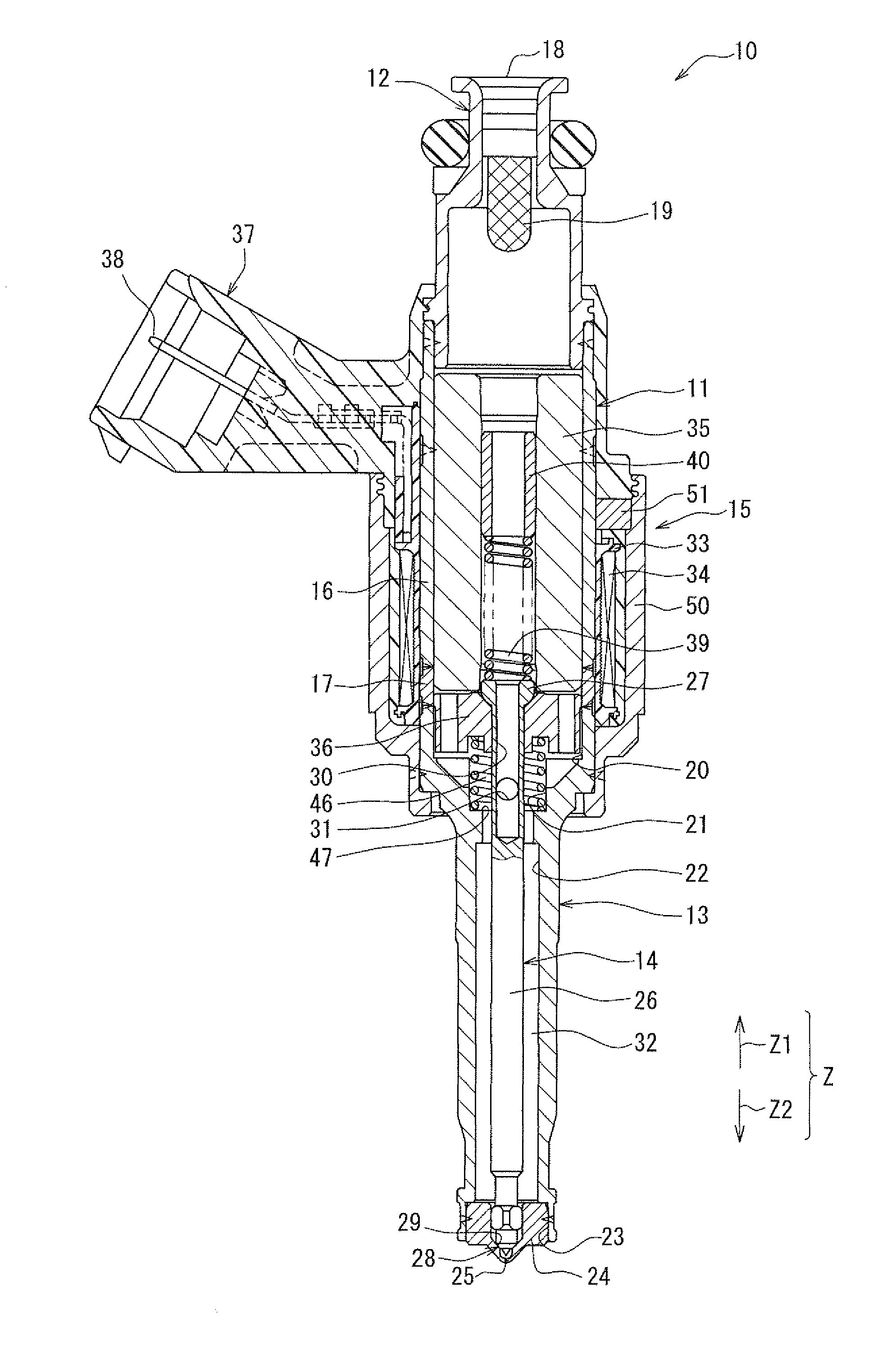
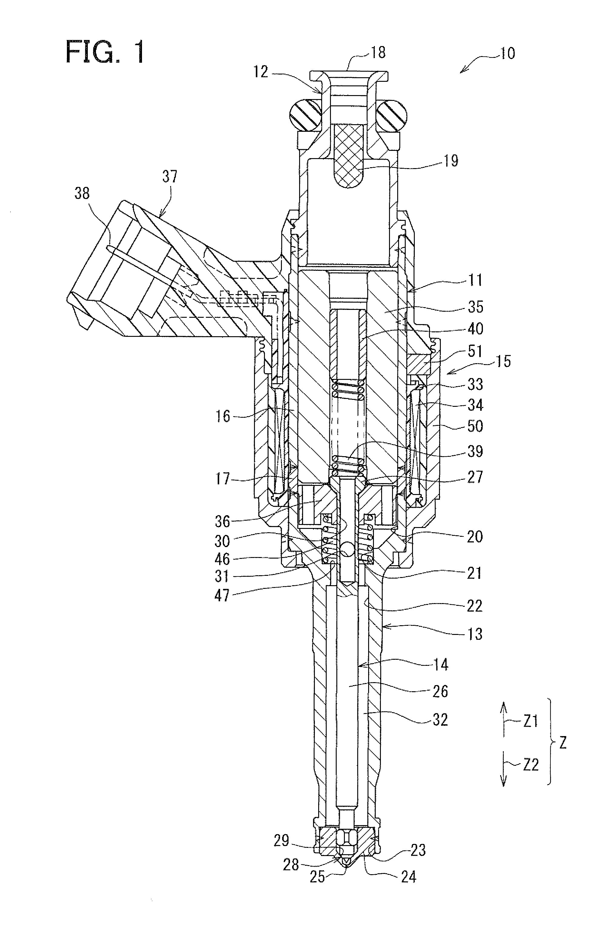
[0036]An injector 10 illustrated in FIG. 1 is an fuel injection valve, and applied for example, to a direct injection type gasoline engine. When the injector 10 is applied to the direct injection type gasoline engine, the injector 10 is disposed in an engine head (not shown).

[0037]The injector 10 includes a cylindrical member 11, an inlet member 12, a nozzle holder 13, a needle 14, and a driving unit 15. The cylindrical member 11 extends in a predetermined axial direction Z (opening and closing direction). The inlet member 12 is disposed at one end part of the cylindrical member 11 in the axial direction Z of the cylindrical member 11. The nozzle holder 13 is disposed at the other end part of the cylindrical member 11 in the axial direction Z of the cylindrical member 11. The needle 14 is accommodated in the injector 10 so as to reciprocate inside the injector 10 in the axial direction Z...

second embodiment

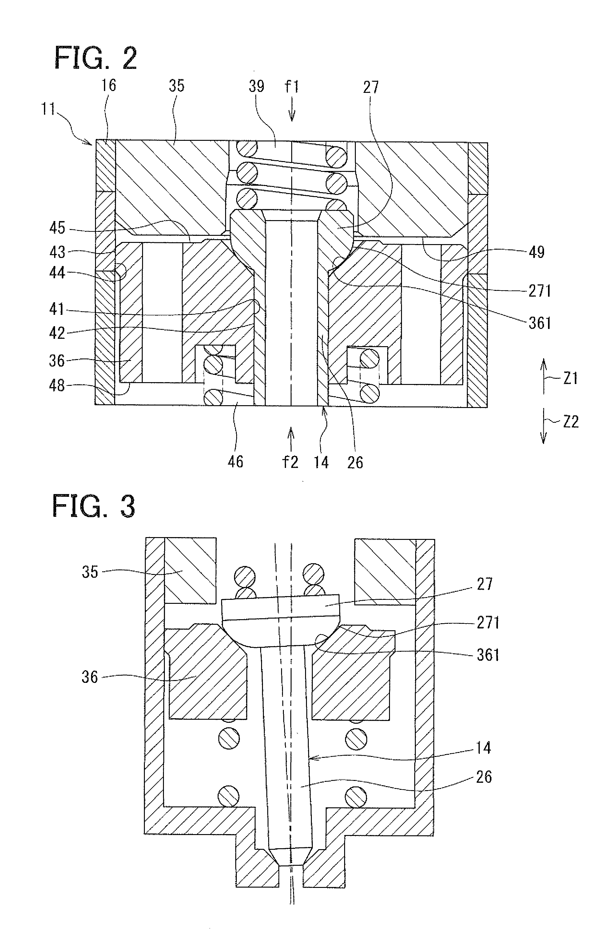
[0092]Similar to the first embodiment, in a second embodiment of the invention, an outer peripheral surface portion 42 of a shaft portion 26 that extends in an axial direction of a needle 14 is slidably guided by an inner peripheral surface portion 410 of an insertion hole 41 that passes through a radially central part of a movable core 36 in the axial direction. The outer peripheral surface portion 42 has a cylindrical surface which extends straight in the axial direction of the needle 14 and whose diameter does not change. The inner peripheral surface portion 410 has a cylindrical surface which extends straight in the axial direction of the movable core 36 and whose diameter does not change. Accordingly, as illustrated with emphasis in FIG. 4, an inner clearance 70, which is located radially inward of the movable core 36, is formed radially as a slide clearance between the outer peripheral surface portion 42 and the inner peripheral surface portion 410.

[0093]The outer peripheral s...

third embodiment

[0104]As illustrated in FIG. 9, in the third embodiment of the invention as a modification of the second embodiment, a stopper inclined surface 1272, which is provided on a surface of a stopper 27 on a movable core 36 side, is formed in a form of the spherically-shaped curved surface in accordance with the first embodiment instead of the shape of the flat inclined surface. More specifically, the stopper inclined surface 1272, which inclines radially inward of the stopper 27 further in a valve closing direction Z2 of an axial direction Z, is formed around an axis 260 of a shaft portion 26 as a curved surface having an R-section. A diameter of the R-section is reduced further in the valve closing direction Z2, and this diameter reduction ratio increases further in the valve closing direction Z2. Accordingly, a movable core inclined surface 362 of the movable core 36 in the shape of a curved surface is in contact with the stopper inclined surface 1272 in the shape of a curved surface, ...


PUM


Abstract

An injector includes a housing, a fixed core, a movable core, a valve member, and a resilient member pressing the valve member toward a nozzle hole. An inner peripheral surface of the housing axially guides an outer peripheral surface of the movable core. The inner peripheral surface and the outer peripheral surface define an outer clearance therebetween. The valve member includes a shaft-shaped portion and a stopper portion, which contacts the movable core and has a stopper inclined surface. An outer peripheral surface of the shaft-shaped portion and an inner peripheral surface of an insertion hole of the movable core define an inner clearance therebetween. The stopper inclined surface inclines radially inward of the shaft-shaped portion axially toward the nozzle hole. An axial clearance is formed between the stopper inclined surface and the movable core radially outward of a contact portion between the stopper inclined surface and the movable core.

Description

CROSS REFERENCE TO RELATED APPLICATION[0001]This application is based on and incorporates herein by reference Japanese Patent Application No. 2009-52458 filed on Mar. 5, 2009 and Japanese Patent Application No. 2009-269063 filed on Nov. 26, 2009.BACKGROUND OF THE INVENTION[0002]1. Field of the Invention[0003]The present invention relates to, for example, an injector that injects and supplies fuel into an internal combustion engine.[0004]2. Description of Related Art[0005]As a conventional technology, an injector is described in a publication of JP-A-2007-278218 (corresponding to US2007 / 0235669A1). This injector includes a moving core and a needle serving as a valve member, and the moving core and the needle are provided independently of each other. The moving core slides in an axial direction of a housing relative to a fixed core. The needle slides in the axial direction of the housing in synchronization with the moving core so as to open and close an injection hole of the housing.[...

Claims


Application Information

Patent Timeline
IPC IPC(8): B05B1/30
CPCF02M51/0675F02M51/0685F02M2200/02F02M61/12F02M61/042
Inventor YAMAMOTO, KAZUOYAMASHITA, JUN
Owner DENSO CORP
Why Eureka
Try Eureka