Diversion Conduit

a technology of diversion conduit and conduit body, which is applied in the direction of hose connection, pipe element, pipe connection arrangement, etc., can solve the problems of requiring further improvement, affecting the use effect, and venerable diversion conduit body, etc., and achieves the effect of convenient use, simple structure and convenient us

Inactive Publication Date: 2011-03-10
TONG ZENGYAO
View PDF17 Cites 4 Cited by
  • Summary
  • Abstract
  • Description
  • Claims
  • Application Information

AI Technical Summary

Benefits of technology

[0004]The purpose of this utility model is to overcome the imperfection of the existing diversion conduit and to provide a newly structured diversion conduit. The technical problem to be solved is to make its structure simple and render it easy to use with detachably connected conduit body and connector so that once the conduit body fractures, its use can be restored, which makes it more suitable to utilize.
[0011]To sum up, this utility model makes only slight improvement to the prior art, being structurally simple and convenient to use. The connections between the conduit body and connectors are detachable. Use can be restored once the conduit body is fractured, greatly avoiding waste, which, consistent with cost effectiveness, is suitable to be promoted to wide application. This utility model has the above advantages and utility value with great improvements in both the structure and function and obvious improvement in technique, producing easy-to-use and practical effect. The improved function compared with the existing diversion conduit renders it more suitable to utilize.

Problems solved by technology

However, practice finds that the difference between the conduit body and the connector in material and structure renders the conduit body venerable to fracture at the connection with the connector, and that the connection between the conduit body and the connector is a fixed and dead connection.
Once the conduit body fractures, the entire diversion conduit will be useless, causing great waste.
It shows that the above existing diversion conduit is obviously in convenient and imperfect in structure and use, which requires further improvement.

Method used


Image

  • Diversion Conduit
  • Diversion Conduit
  • Diversion Conduit

Examples


Embodiment Construction

[0015]To further elaborate on the technical approach and function to achieve the purpose of this utility model, he above and other purposes, features, and advantages of the this utility model will be described and become more apparent from the detailed description of preferred embodiments when read in conjunction with the drawings and preferred embodiment will be referred to describe in detail the diversion conduit proposed according to this utility model in terms of the embodiment, structure, characteristics and effect.

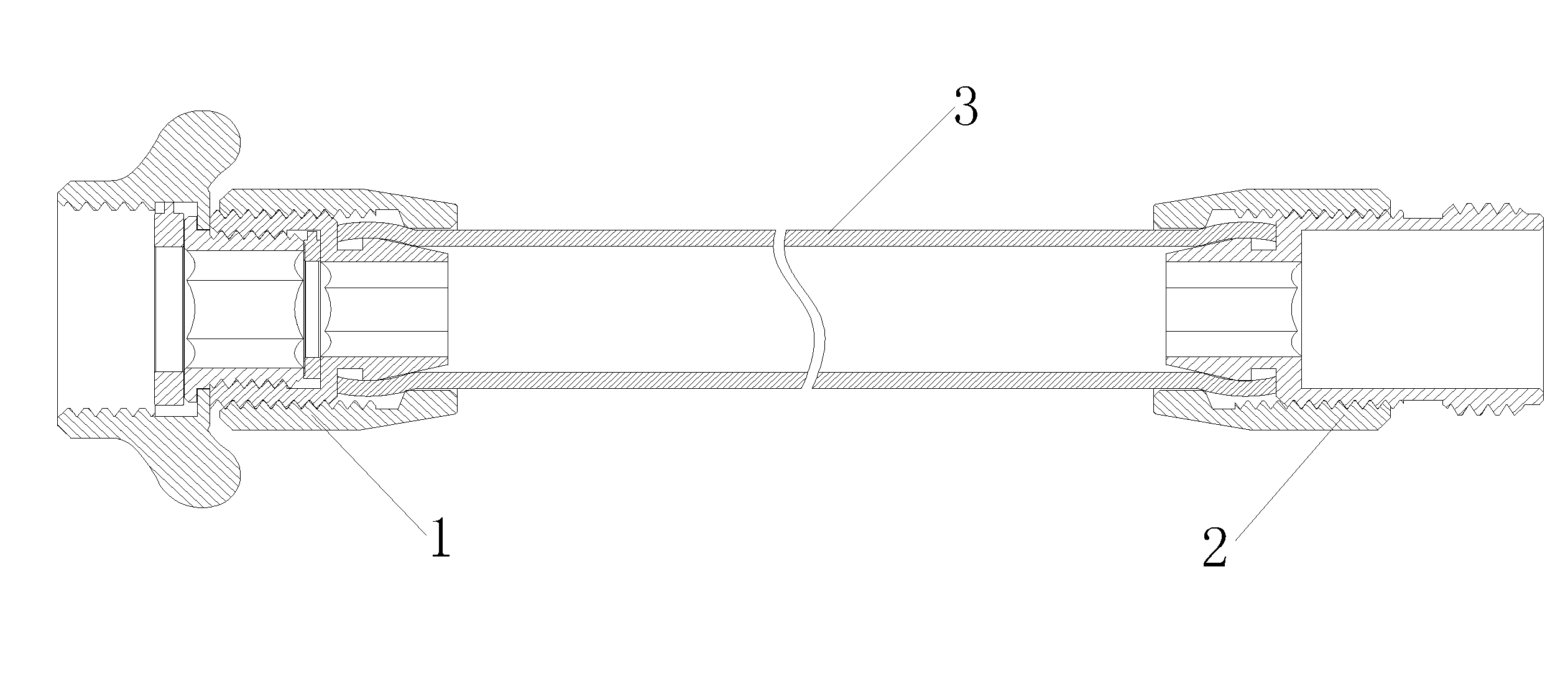
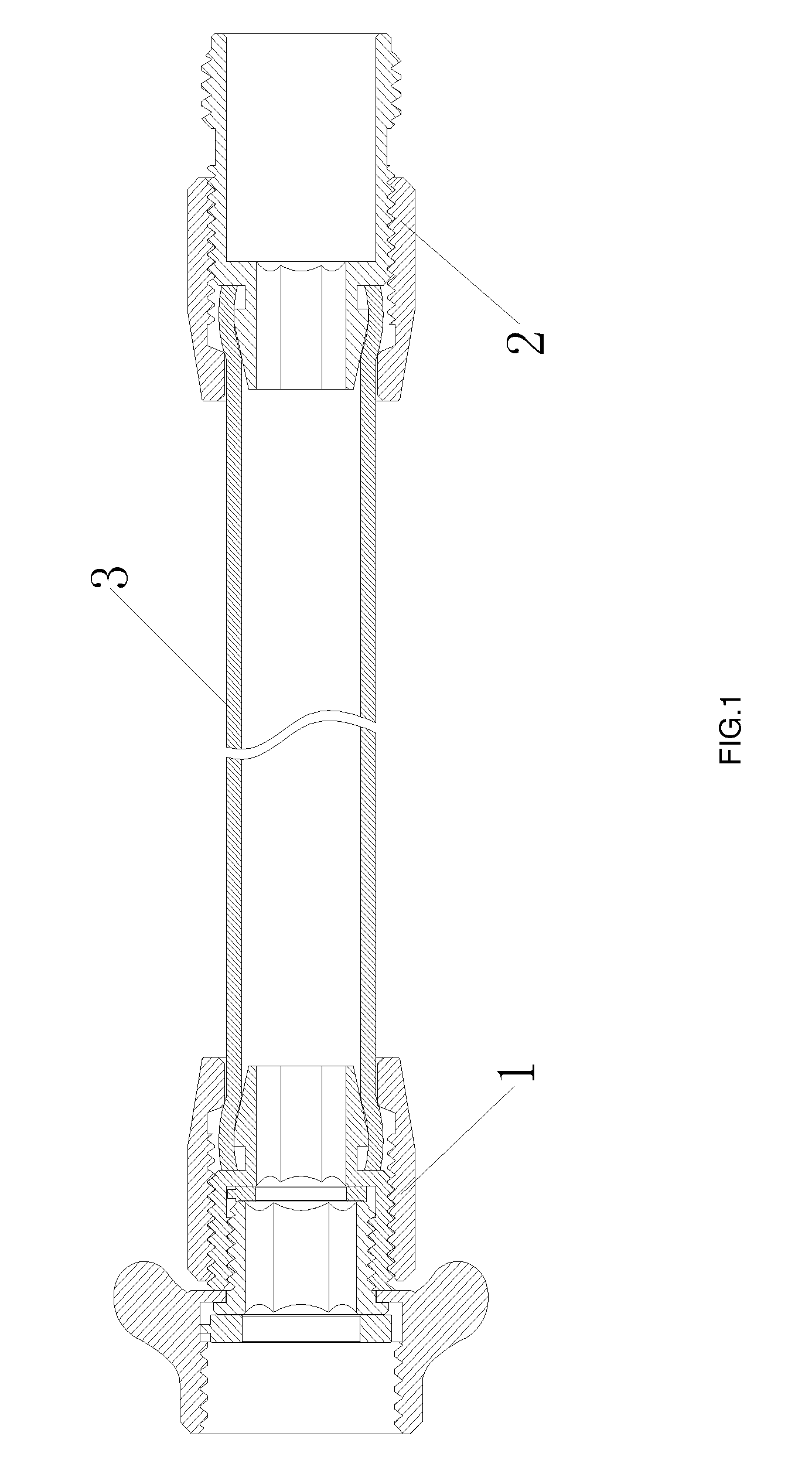
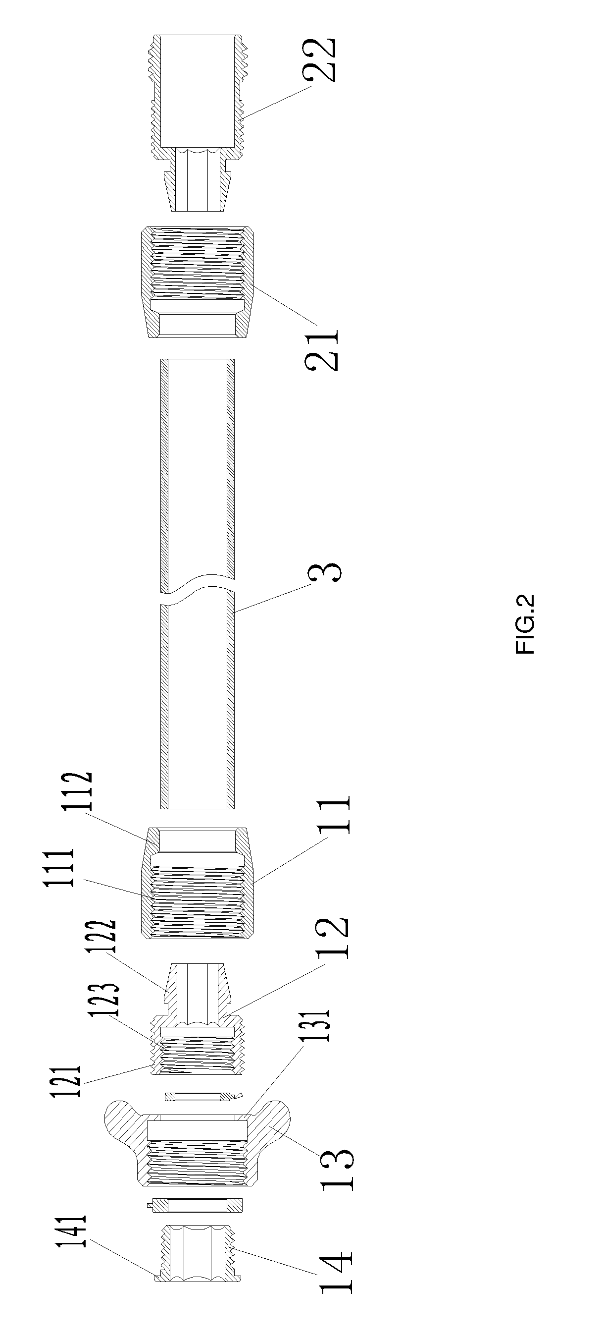
[0016]FIG. 1 and FIG. 2 show that this utility model comprises water intake connector (1), water output connector (2) and conduit body (3). The connection of conduit body (3) with water intake connector (1) and with water output connector (2) is detachable.

[0017]Wherein, the water intake connector (1) mainly includes the external cap (11) and the internal calipers (12). The external cap (11) includes the internal threads (111) and the internal projection (112). The m...


PUM

PropertyMeasurementUnit
diameteraaaaaaaaaa
internal diameteraaaaaaaaaa
structureaaaaaaaaaa

Abstract

This utility model relates to a diversion conduit, comprising of a water intake connector, a water output connector and a conduit body. The said water intake connector and water output connector each include a detachably connected external cap and internal calipers. The end of the conduit body is clamped between the external cap and internal calipers. This utility model makes only slight improvement to the prior art, being structurally simple and convenient to use. The connections between the conduit body and connectors are detachable. Use can be restored once the conduit body is fractured, greatly avoiding waste, which, consistent with cost effectiveness, is suitable to be promoted to wide application.

Description

BACKGROUND OF THE INVENTION[0001]This utility model relates to a diversion conduit and particularly to a diversion conduit commonly used for irrigating the greening.[0002]There are a variety of irrigation systems for existing flower beds, lawns and other greening facilities. One of them is to use a diversion conduit to connect the water tap for irrigation; this kind of irrigation system is most common and simple to construct with low cost, and finds the widest application. However, practice finds that the difference between the conduit body and the connector in material and structure renders the conduit body venerable to fracture at the connection with the connector, and that the connection between the conduit body and the connector is a fixed and dead connection. Once the conduit body fractures, the entire diversion conduit will be useless, causing great waste.[0003]It shows that the above existing diversion conduit is obviously in convenient and imperfect in structure and use, whi...

Claims


Application Information

Patent Timeline
Patent Type & Authority Applications(United States)
IPC IPC(8): F16L55/00
CPCF16L47/04F16L33/223F16L47/041
Inventor TONG, ZENGYAO
Owner TONG ZENGYAO
Why Eureka
Try Eureka