Liquid crystal display device including edge-type backlight unit and method of controlling the liquid crystal display

a liquid crystal display and edge-type backlight technology, applied in the direction of electric digital data processing, instruments, computing, etc., can solve the problem that the viewer may become fatigued while watching a 3d imag

Inactive Publication Date: 2011-03-10
SAMSUNG ELECTRONICS CO LTD
View PDF8 Cites 19 Cited by
  • Summary
  • Abstract
  • Description
  • Claims
  • Application Information

AI Technical Summary

Benefits of technology

[0027]According to an aspect of another exemplary embodiment, there is provided an LCD device including: an LCD panel; an edge-type backlight unit in which light sources are disposed at upper and lower edges of the edge-type backlight unit; an LCD panel control unit controlling the LCD panel such that a left image and a right image of a 3D image are alternately output on the LCD panel; and a backlight control unit classifying the light sources of the edge-type backlight unit into upper light sources including light sources disposed at the upper edge of the edge-type backlight unit and lower lig

Problems solved by technology

Thus, the left eye and the right eye of the viewer see a distorted image due to the cross-talk, and the viewer may become fatigued watching a 3D image.
Also, an ex

Method used


Image

  • Liquid crystal display device including edge-type backlight unit and method of controlling the liquid crystal display
  • Liquid crystal display device including edge-type backlight unit and method of controlling the liquid crystal display
  • Liquid crystal display device including edge-type backlight unit and method of controlling the liquid crystal display

Examples


Embodiment Construction

[0040]Certain exemplary embodiments are described in greater detail below with reference to the accompanying drawings.

[0041]In the following description, like drawing reference numerals are used for the like elements, even in different drawings. The matters defined in the description, such as detailed construction and elements, are provided to assist in a comprehensive understanding of exemplary embodiments. However, exemplary embodiments can be practiced without those specifically defined matters.

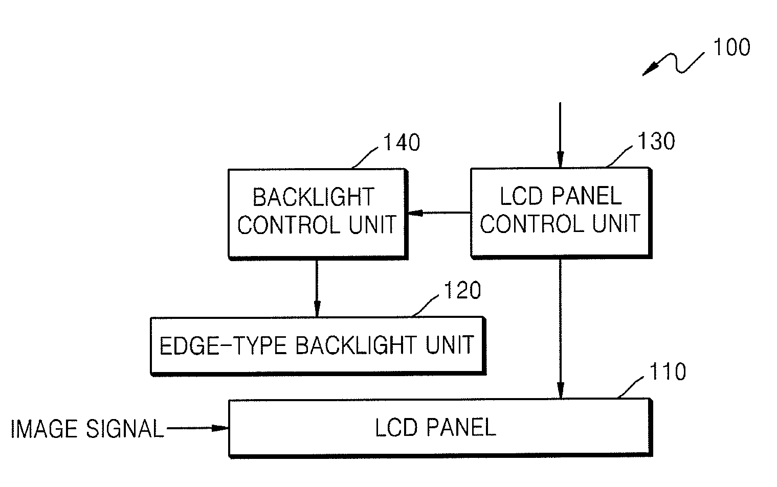
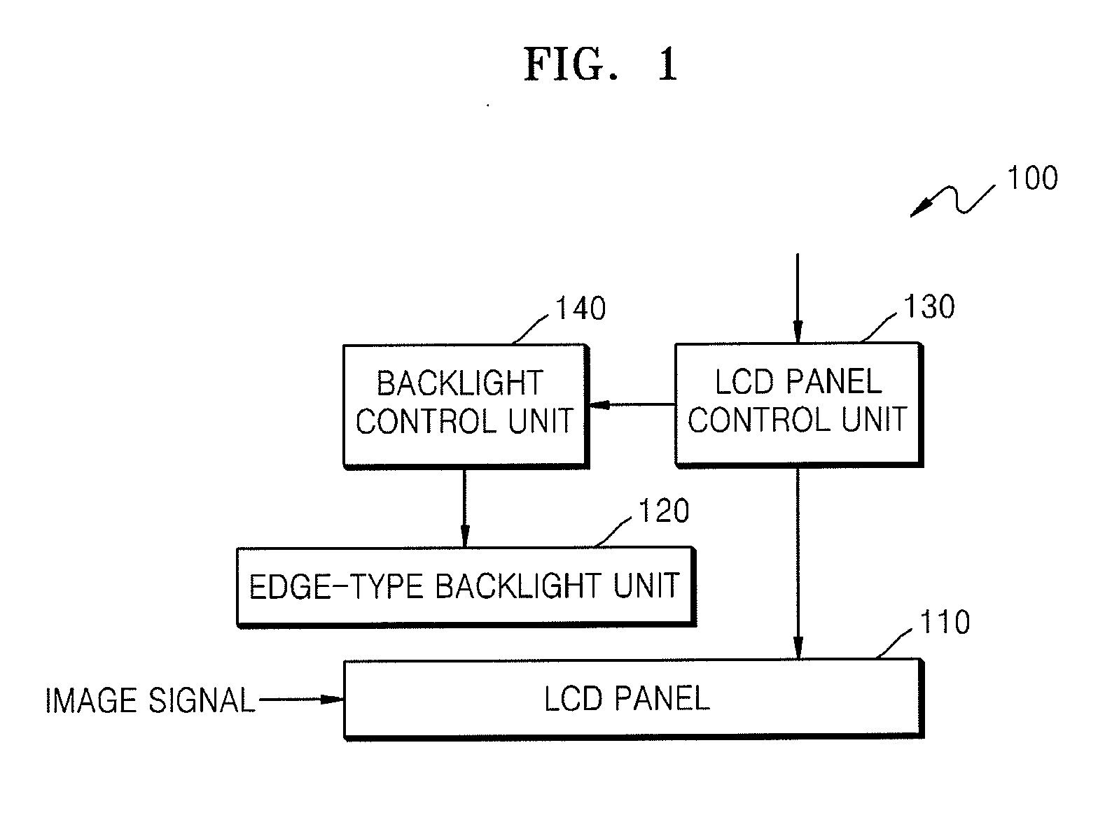
[0042]FIG. 1 illustrates a block diagram of an LCD device 100 including an edge-type backlight unit 120, according to an exemplary embodiment.

[0043]The LCD device 100 includes an LCD panel 110, an edge-type backlight unit 120, an LCD panel control unit 130, and a backlight control unit 140 for controlling light sources of the edge-type backlight unit 120.

[0044]The LCD panel 110 receives an image signal and outputs the image signal on a screen. The LCD device 100 outputs a 3D image signal t...


PUM


Abstract

A method of controlling a liquid crystal display (LCD) device including an LCD panel and an edge-type backlight unit is provided. The method includes: controlling turn-on and turn-off periods of an upper light source unit and a lower light source unit of the edge-type backlight unit to be synchronized with a period during which a 3D image is output on the LCD panel, wherein the upper light source unit includes a light source disposed at an upper edge of the edge-type backlight unit, and the lower light source unit includes a light source disposed at a lower edge of the edge-type backlight unit.

Description

CROSS-REFERENCE TO RELATED PATENT APPLICATIONS[0001]This application claims priority from U.S. Provisional Application No. 61 / 239,835, filed Sep. 4, 2009, and Korean Patent Application No. 10-2009-0104424, filed Oct. 30, 2009, in the Korean Intellectual Property Office, the disclosures of which are incorporated herein in their entirety by reference.BACKGROUND[0002]1. Field[0003]Apparatuses and methods consistent with exemplary embodiments relate to a liquid crystal display (LCD) devices.[0004]2. Description of the Related Art[0005]Three-dimensional (3D) image display devices which display stereoscopic images have been recently developed. A stereoscopic image is generated by the stereoscopic viewing principle of human's eyes, and binocular parallax, which is the apparent difference in position of an object as seen separately by the human eyes separated by a distance of approximately 65 mm. By showing images which are the same as actually seen by the eyes, stereoscopic depth can be pr...

Claims


Application Information

Patent Timeline
IPC IPC(8): G09G3/36G09G5/10
CPCG09G3/003G09G2310/0237G09G2320/0209G09G3/3406G09G3/342G09G3/36
Inventor PARK, SANG-MOOYOON, JUNG-HOONKIM, DAE-SIKLEE, HO-SEOPJUNG, JONG-HOON
Owner SAMSUNG ELECTRONICS CO LTD
Why Eureka
Try Eureka