Structure, method of forming structure, method of laser processing, and method of discriminating between true and false objects

a technology of forming structure and laser processing, applied in the field of structure, can solve the problems of difficult laser making on high-molecular processed products (plastics) which transmit laser light, poor appearance, and inability to draw important data, so as to prevent falsification or erasure of marked parts, improve laser light absorption, and prevent deterioration of coloring

Inactive Publication Date: 2011-03-10
TOYO SEIKAN KAISHA LTD
View PDF5 Cites 3 Cited by
  • Summary
  • Abstract
  • Description
  • Claims
  • Application Information

AI Technical Summary

Benefits of technology

[0048]According to the structural body, the method for forming a structural body, the method for laser processing, and the method for discriminating between true and false objects of the present invention, if a structural body having an outer layer which transmits light with a specific wavelength and an inner layer which does not transmit light with the specific wavelength is irradiated with laser light with the specific wavelength, this laser light transmits the outer layer to reach the inner layer and generates photodecomposition on the surface of the inner layer, whereby a fine periodic structure in the form of convexes and concaves can be formed. As a result, laser marking can be conducted without fail on the second or subsequent layers of a structural body having a multilayer structure.
[0049]Since the first layer serves as a protective layer, a marked part is not exposed to open air. As a result, a marked part can be resistant to marring or fouling, thereby to prevent deterioration of coloring, and further, falsification or erasion of a marked part can be prevented.
[0050]Since marking is formed of a fine periodic structure in the form of concaves and convexes, marking can be conducted in various colors which are equivalent to those of a hologram.
[0051]According to the structural body, the method for forming a structural body, the method for laser processing, and the method for discriminating between true and false objects of the present invention, a high-molecular compound constituting an object to be processed is modified by irradiation of light, and the laser light absorptivity can be enhanced. As a result, even in the case of an object to be processed which contains a high-molecular compound which transmits laser light in at least one part thereof, laser marking can be conducted easily on this high-molecular compound.
[0052]Furthermore, since laser light absorptivity is increased by light irradiation, there is no need to use a light-absorbing agent, which prevents an increase in cost. In addition, since there is no need to disperse or apply a light-absorbing agent, the working process can be simplified.
[0053]Furthermore, since laser light absorptivity is increased by light irradiation, the transparency of an object to be processed is not deteriorated, and hence, the object to be processed can be processed into a product while keeping the transparent state.

Problems solved by technology

Therefore, if the surface is marred or fouled, etc, a good appearance might not be obtained.
Moreover, due to the fear of falsification or erasion, there was also a problem that important data could not be drawn.
Although laser marking is conducted on many industrial products, it is difficult to conduct laser making on a high-molecular processed product (plastics) which transmits laser light.

Method used


Image

  • Structure, method of forming structure, method of laser processing, and method of discriminating between true and false objects
  • Structure, method of forming structure, method of laser processing, and method of discriminating between true and false objects
  • Structure, method of forming structure, method of laser processing, and method of discriminating between true and false objects

Examples


example 1

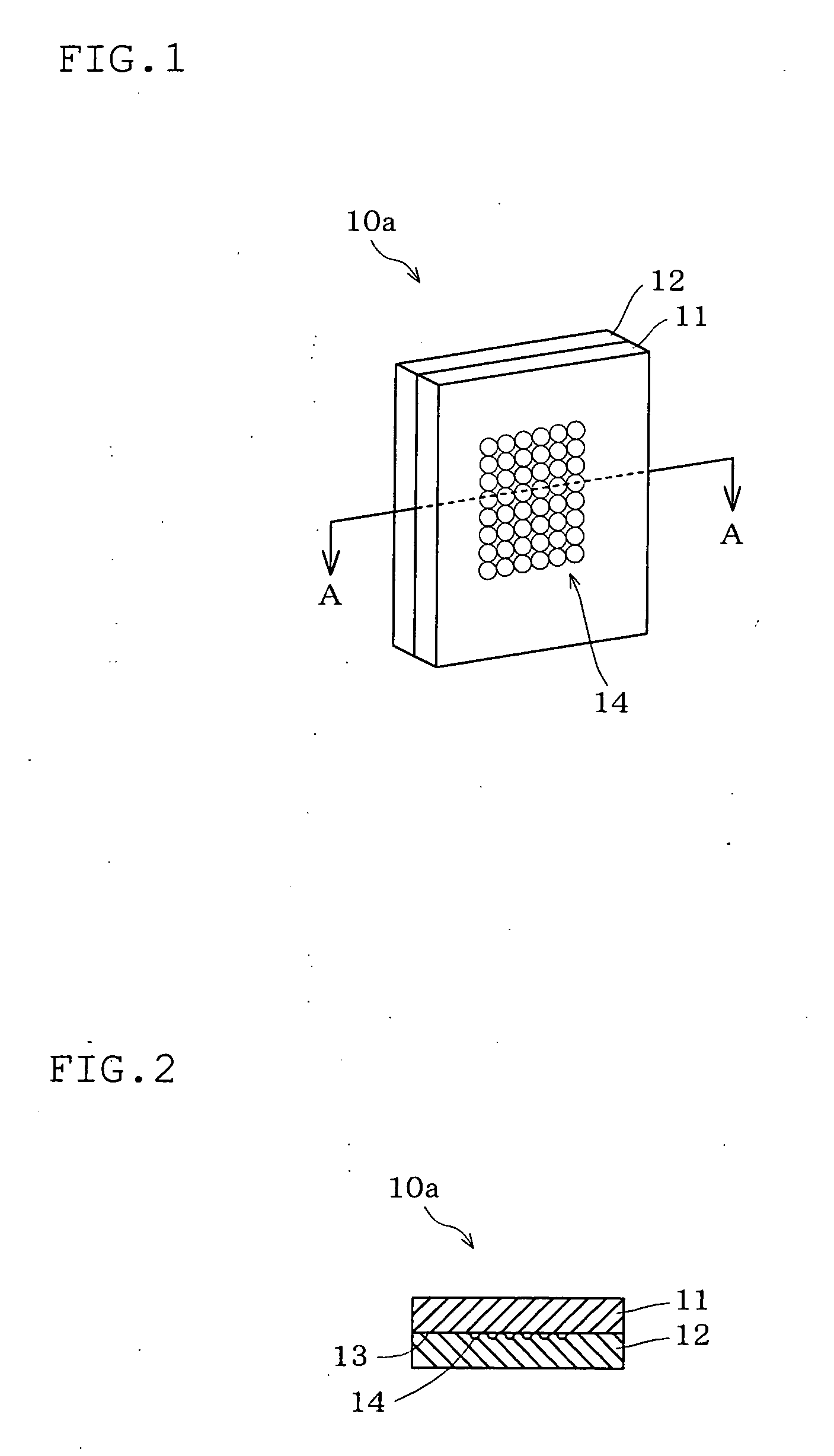
[0222]As the object 10d to be processed, a plurality of elongated PET sheets each having a thickness of 150 μm were prepared.

[0223]Of these elongated PET sheets, one or several sheets were irradiated for 10 minutes with UV rays emitted from a mercury and xenon lamp (manufactured by USHIO, Inc.) which was placed 12 cm away from the sheet.

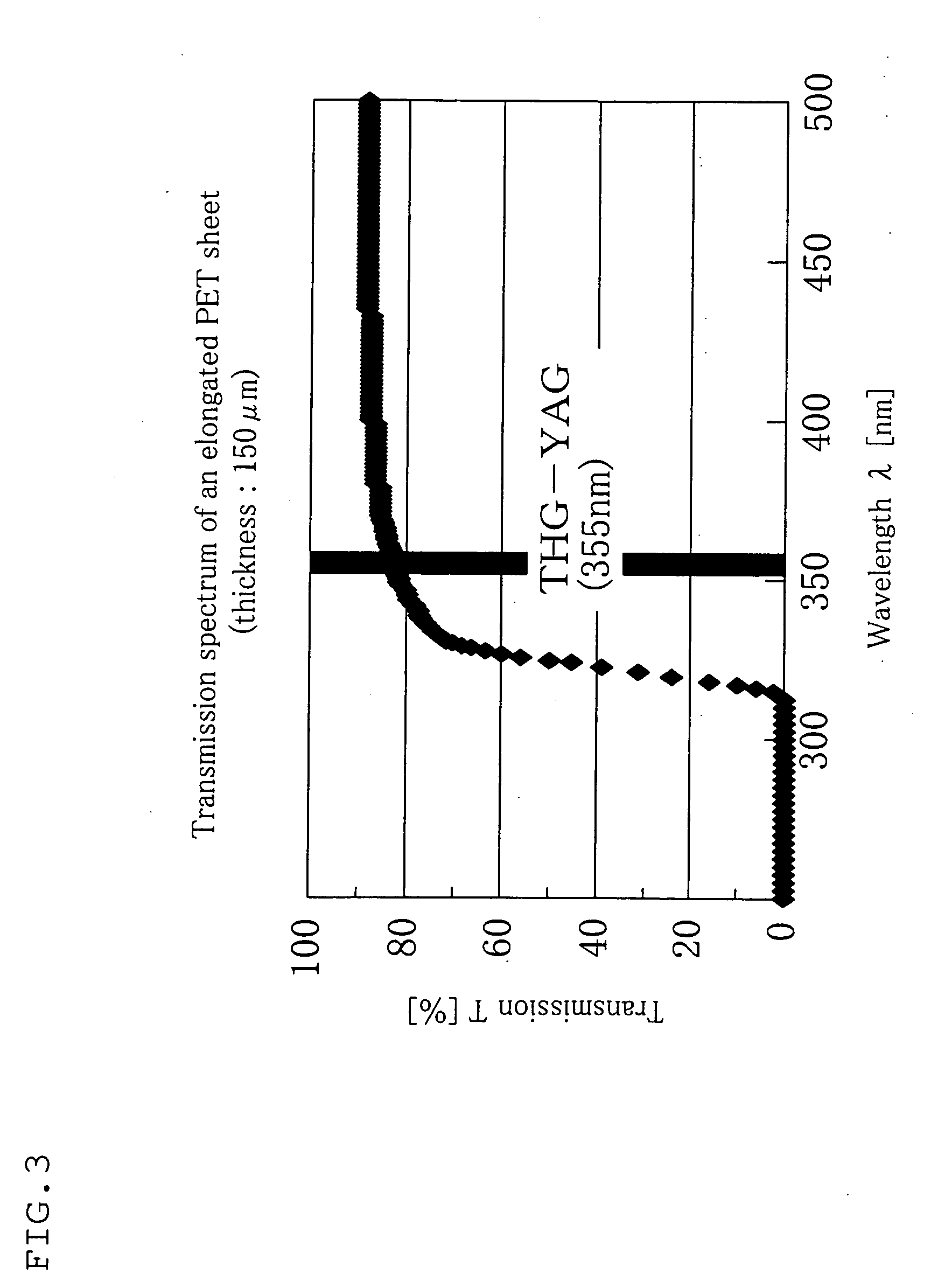
[0224]The transmissibility of the elongated PET sheet for light with a wavelength of 355 nm was measured, and the results revealed that the transmissibility was 82.3% before the irradiation and 76.7% after the irradiation.

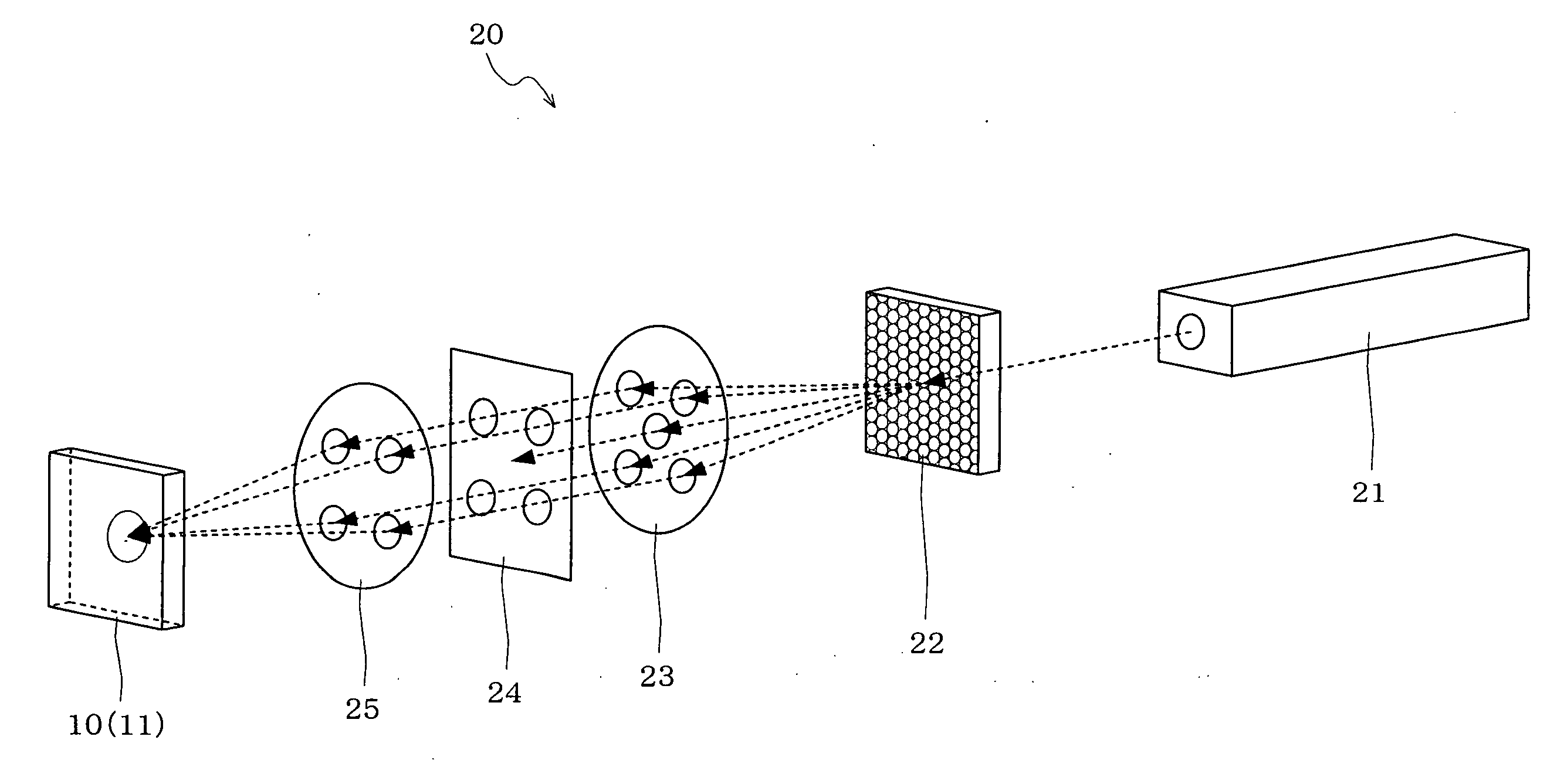
[0225]Subsequently, the above-mentioned elongated PET sheet which had been irradiated with UV rays and an elongated PET sheet which had not been irradiated with UV rays were prepared. These sheets were irradiated with the third harmonic wave of a Q-switch pulse YAG laser (wavelength: 355 nm), which shows transmissibility for an elongated PET sheet, by means of a laser light irradiation apparatus.

[0226]As for the specification of the...

example 2

[0231]As the object 10d to be processed, a plurality of elongated PET sheets each having a thickness of 150 μm was prepared.

[0232]Of these elongated PET sheets, one or several sheets were irradiated for 5 seconds with UV rays emitted from a mercury and xenon lamp (manufactured by USHIO, Inc.) which was placed 55 mm away from the sheet.

[0233]The transmissibility of the elongated PET sheet for light with a wavelength of 355 nm was measured, and the results revealed that the transmissibility was 82.3% before the irradiation and 82.1% after the irradiation.

[0234]Subsequently, the above-mentioned elongated PET sheet which had been irradiated with UV rays and an elongated PET sheet which had not been irradiated with UV rays were prepared. These sheets were irradiated with the third harmonic wave of a Q-switch pulse YAG laser (wavelength: 355 nm), which shows transmissibility for an elongated PET sheet, by means of an interference optical system (laser light irradiation apparatus 20).

[0235...

example 3

[0238]As the object 10d to be processed, four elongated PET sheets each having a thickness of 150 μm were prepared.

[0239]Of these elongated PET sheets, one elongated PET sheet was irradiated with UV rays emitted from a UV lamp (black light) with an emission peak wavelength of 254 nm for 90 minutes. Another elongated PET sheet was irradiated with UV rays emitted from a UV lamp with a wavelength of 302 nm for the same period of time. Still another elongated PET sheet was irradiated with UV rays emitted from a UV lamp with a wavelength of 365 nm for the same period of time. The remaining elongated PET sheet was not irradiated with UV rays emitted from a UV lamp.

[0240]Here, as for the transmissibility of the elongated PET sheet at a wavelength of 355 nm, the non-irradiated sheet showed 82.3%, the sheet irradiated with light with a wavelength of 254 nm was 80.4%, the sheet irradiated with light with a wavelength of 302 nm was 77.9% and the sheet irradiated with light with a wavelength of...


PUM

PropertyMeasurementUnit
wavelengthaaaaaaaaaa
light wavelengthaaaaaaaaaa
distanceaaaaaaaaaa

Abstract

Laser marking is surely conducted on the second and subsequent layers of a structural body with a multilayer structure, whereby a marked part can be prevented from being marred, fouled, falsified or erased, as well as marking can be conducted in a variety of colors.
A structural body 10 including an inner layer 12 and an outer layer 11 stacked, wherein said inner layer 12 is formed of a resin which does not transmit light with a specific wavelength and said outer layer 11 is formed of a resin which transmits light with the specific wavelength, and a fine periodic structure 14 in the form of convexes and concaves formed by generation of photodecomposition is provided on at least part of the surfaces 13 of the inner layer 12 which is opposite to the outer layer 11.

Description

TECHNICAL FIELD[0001]The present invention relates to a structural body which is an object of laser processing, a method for forming a structural body which is the procedure of forming this structural body, a method for laser processing in which a predetermined processing is conducted by irradiating laser light and a method for discriminating between true and false objects utilizing the method for forming a structural body and the method for laser processing. In particular, the present invention relates to a structural body on which marking is made by the irradiation of laser light, a method for forming a structural body and a method for discriminating between true and false objects.BACKGROUND ART[0002]Laser marking is a technique of providing various industrial products with characters, signs, markings, etc. by irradiating laser light.[0003]Due to such advantages as good appearance, almost no possibility of being deteriorated, a short processing time, and labor-saving properties, t...

Claims


Application Information

Patent Timeline
Patent Type & Authority Applications(United States)
IPC IPC(8): G01J3/46B23K26/00B32B1/00
CPCB29C2791/009B23K2203/18Y10T428/24628B23K26/06B32B27/16B23K26/4065B23K26/0084B23K2203/16B32B27/36B23K26/0057G07D7/124B23K26/362B23K26/53B23K26/355B23K2103/172B23K2103/18B23K2103/42B23K2103/50G07D7/003
Inventor YUASA, YOSHIYUKITAKENOUCHI, KENKURODA, HITOMIHIRAKAWA, NOBUOHOSONO, HIROKO
Owner TOYO SEIKAN KAISHA LTD
Why Eureka
Try Eureka