
Apparatus for contacting hydrocarbon feed and catalyst

Inactive Publication Date: 2011-03-10
UOP LLC
View PDF18 Cites 7 Cited by
  • Summary
  • Abstract
  • Description
  • Claims
  • Application Information

AI Technical Summary

Benefits of technology

[0005]We have found that in larger FCC units, hydrocarbon feed from the feed injectors does not penetrate through the flowing catalyst to the center of the riser. Consequently, a high density core of catalyst can develop in the ri

Problems solved by technology

The high density core can be very stable and exist while ascending through a significant height of the riser resulting in lack of conversion and poorer selectivity to desirable products.

Method used


Image

  • Apparatus for contacting hydrocarbon feed and catalyst
  • Apparatus for contacting hydrocarbon feed and catalyst
  • Apparatus for contacting hydrocarbon feed and catalyst

Examples


Embodiment Construction

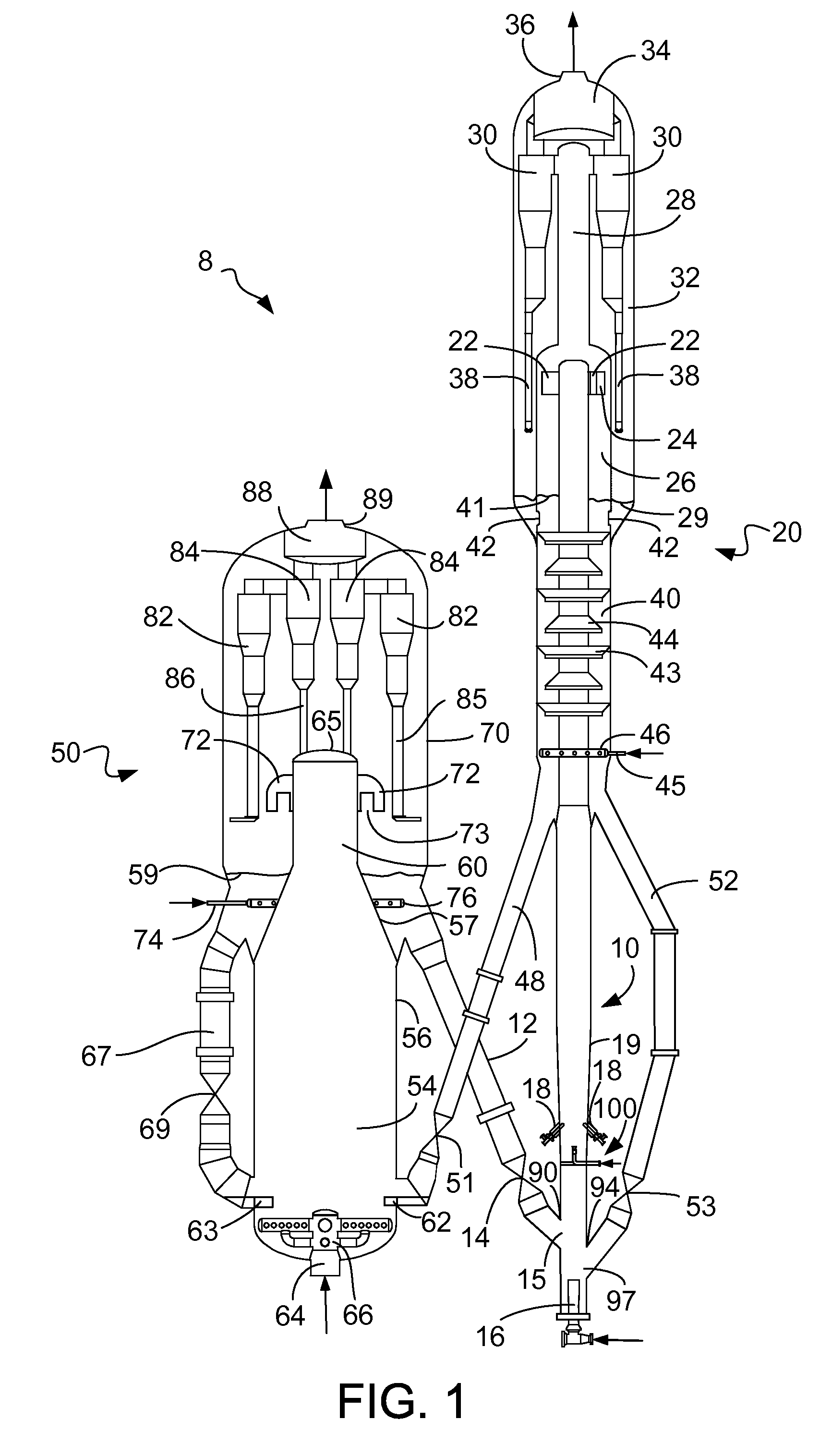
[0010]The apparatus of the present invention is for contacting catalyst with a hydrocarbon feed. The present invention may be useful in any solids-gas contacting equipment. However, ready usefulness is found in an FCC unit.

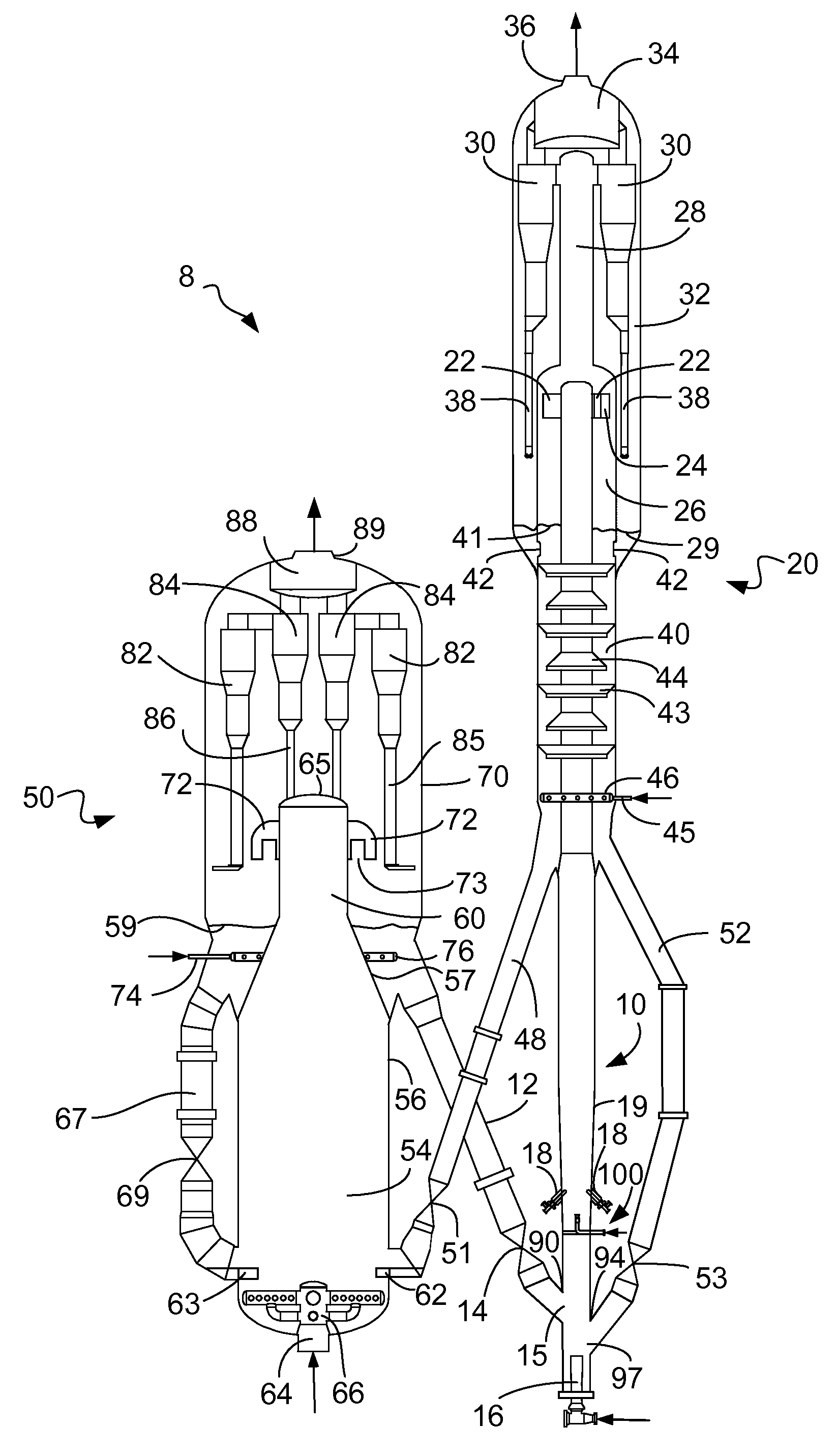
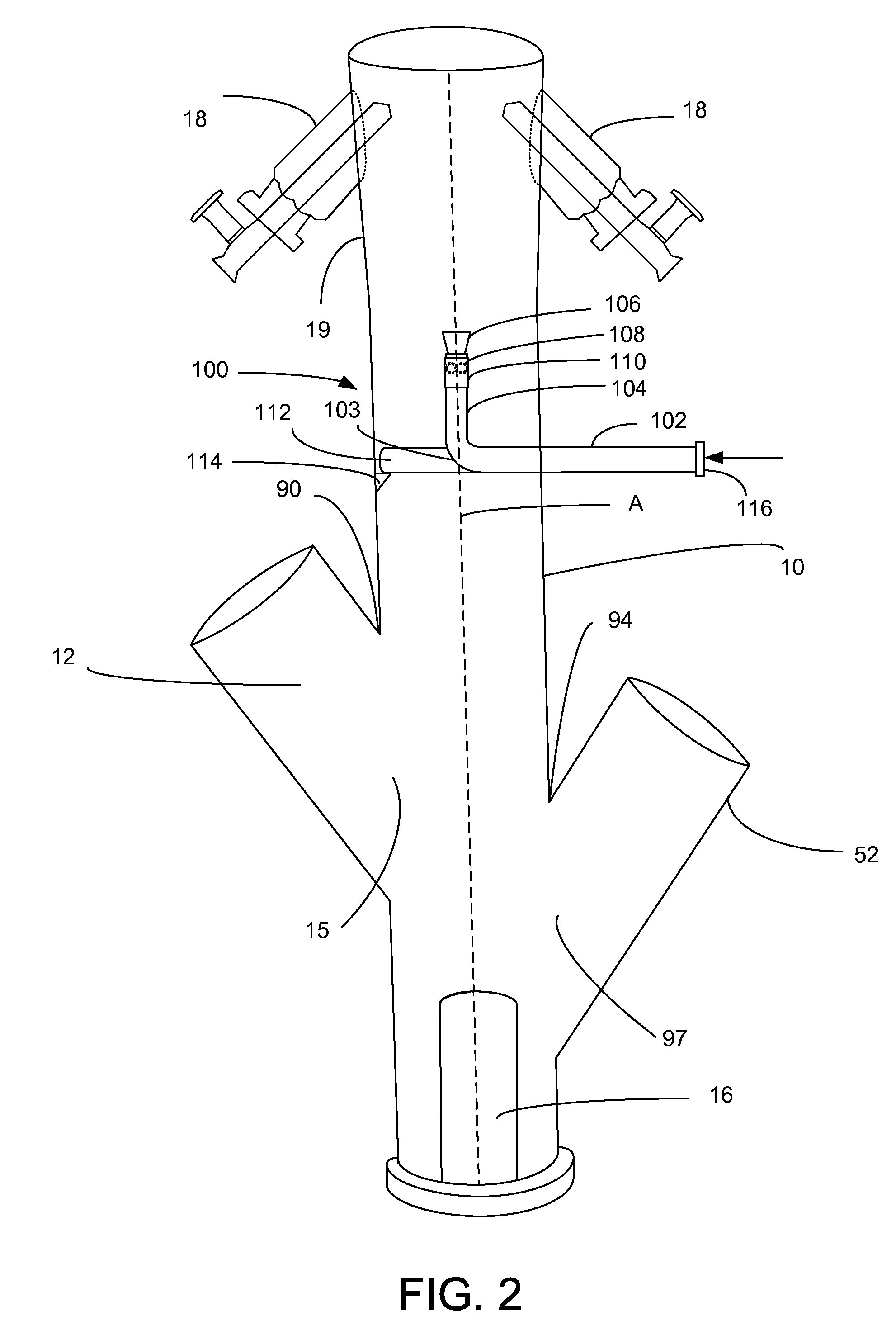
[0011]FIG. 1 shows an FCC unit 8 that includes a reactor vessel 20 and a regenerator vessel 50. A regenerator catalyst conduit 12 transfers regenerated catalyst from the regenerator vessel 50 at a rate regulated by a control valve 14 to a reactor riser 10 through a regenerated catalyst inlet 15. The regenerated catalyst conduit 12 intersects the reactor riser 10 at a regenerated catalyst conduit intersection 90, which is the highest point at which the regenerated catalyst conduit intersects the riser 10. A lift gas distributor 16 distributes lift gas to the riser 10. The lift gas is typically steam, but other light hydrocarbons or hydrogen may be used. The lift gas urges a stream of catalyst upwardly through the riser 10 at a relatively high density traveling at l...


PUM


Abstract

An apparatus for distributing a deflecting media into an axial center of a riser to push catalyst outwardly toward the feed injectors ensures better contacting between hydrocarbon feed and catalyst.

Description

BACKGROUND OF THE INVENTION[0001]The invention relates to an apparatus for mixing hydrocarbon feed and catalyst. A field of the invention may be the field of fluid catalytic cracking (FCC).[0002]FCC is a hydrocarbon conversion process accomplished by contacting hydrocarbons in a fluidized reaction zone with a catalyst composed of finely divided particulate material. The reaction in catalytic cracking, as opposed to hydrocracking, is carried out in the absence of substantial added hydrogen or the consumption of hydrogen. As the cracking reaction proceeds substantial amounts of highly carbonaceous material referred to as coke are deposited on the catalyst to provide coked or carbonized catalyst. This carbonized catalyst is often referred to as spent catalyst. However, this term may be misconstrued because the carbonized catalyst still has significant catalytic activity. Vaporous products are separated from carbonized catalyst in a reactor vessel. Carbonized catalyst may be subjected t...

Claims


Application Information

Patent Timeline
IPC IPC(8): B01J8/18
CPCB01J4/002C10G11/18B01J8/085B01J4/005B01J8/1818B01J8/1827B01J8/1872B01J8/26
Inventor COUCH, KEITH A.PALMAS, PAOLOLAMBIN, JASON P.SPINELLI, GIOVANNI
Owner UOP LLC
Learn More