
Valve connector for medical lines

Active Publication Date: 2011-03-10
IND BORLA
View PDF23 Cites 31 Cited by
  • Summary
  • Abstract
  • Description
  • Claims
  • Application Information

AI Technical Summary

Benefits of technology

[0010]A further functional advantage lies in the fact that, when the female fitting is engaged by screwing within the rotatable external tubular element of the male inlet fitting of the tubular body, following upon initial axial displacement of the female fitting, the passage of flow through the valve connector is already open. Subsequent screwing between the rotatable external tubular element of the male inlet fitting and the female fitting produces a further displacement of overtravel of the internal tubular element beyond the aforesaid advanced position of opening of the passage of flow so that the flowrate of the fluid that flows through the connector is the same during the entire step of connection between the male fitting of the tubular body and the female fitting.
[0011]Furthermore, the voluntary operation of coupling or uncoupling between the female fitting and the tubular body is facilitated by the rotation of the external tubular element of the male fitting of the tubular body, which prevents any torsion of one and / or other section of the medical line to which the connector is associated in use.

Problems solved by technology

In the eventuality where, during use of the connector, there accidentally occurs unscrewing between the female fitting and the male inlet fitting of the tubular body, the section of the medical line connected to said female fitting (which, as has been said, in the case of a haemodialysis line, is the section connected to the patient) is subject to the risk of uncontrolled opening.

Method used


Image

  • Valve connector for medical lines
  • Valve connector for medical lines
  • Valve connector for medical lines

Examples


Embodiment Construction

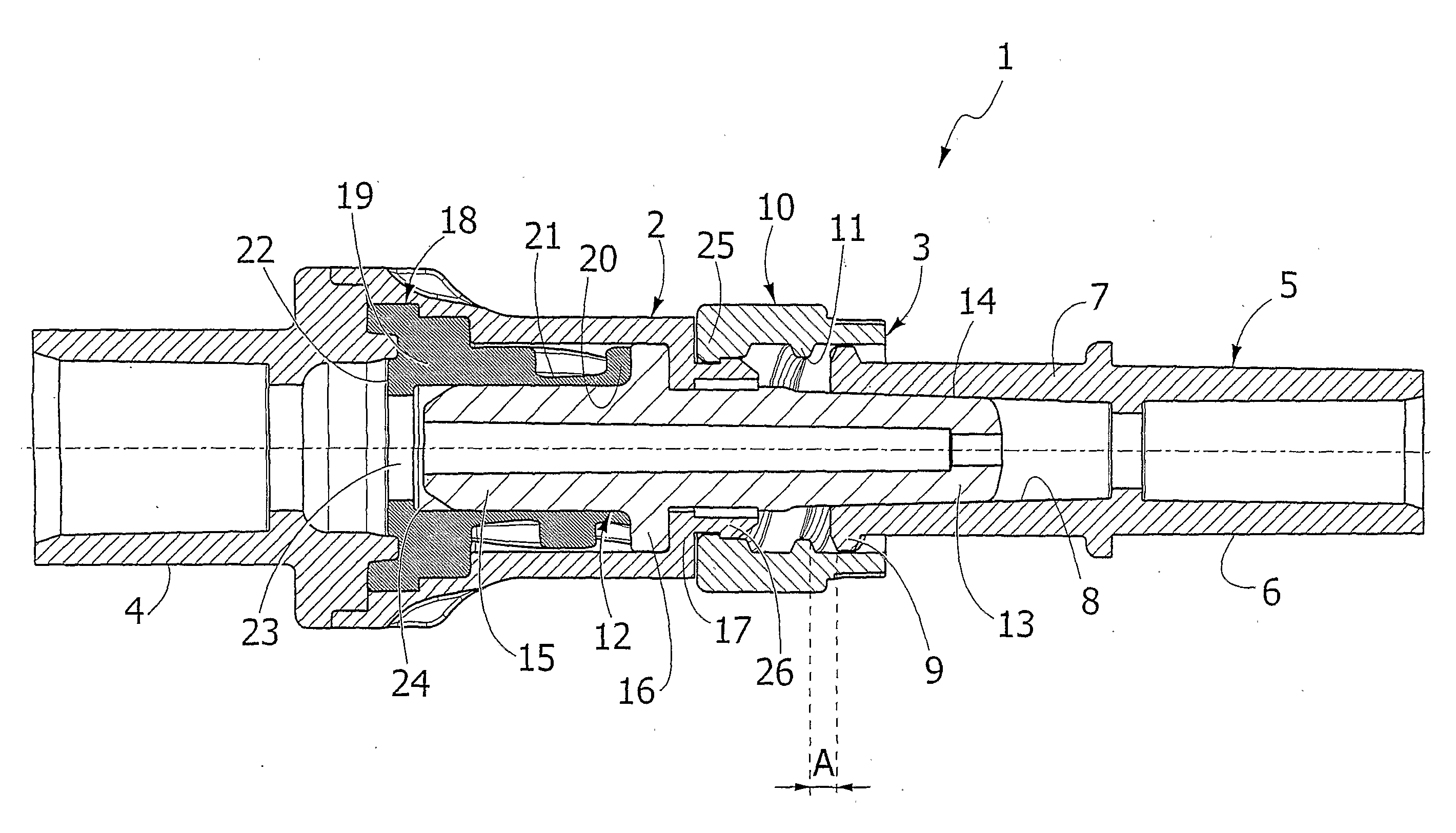
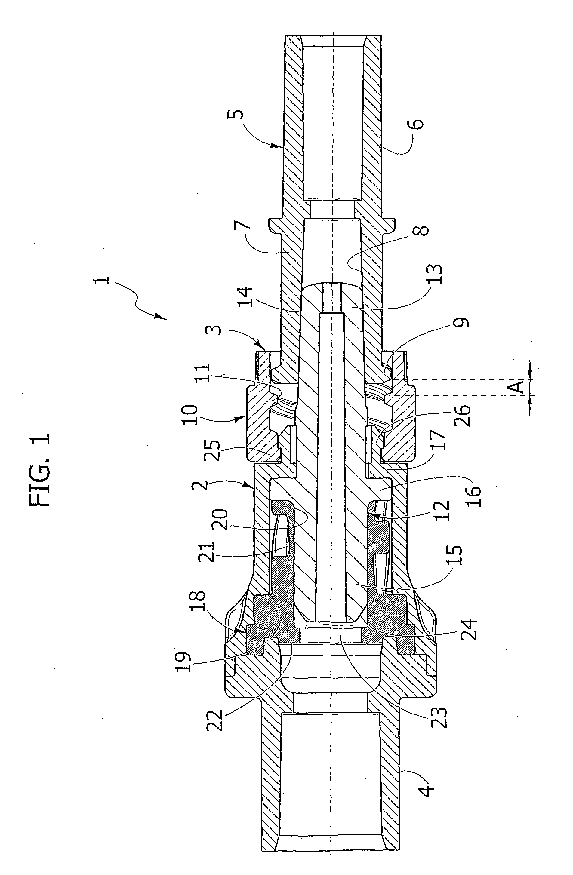
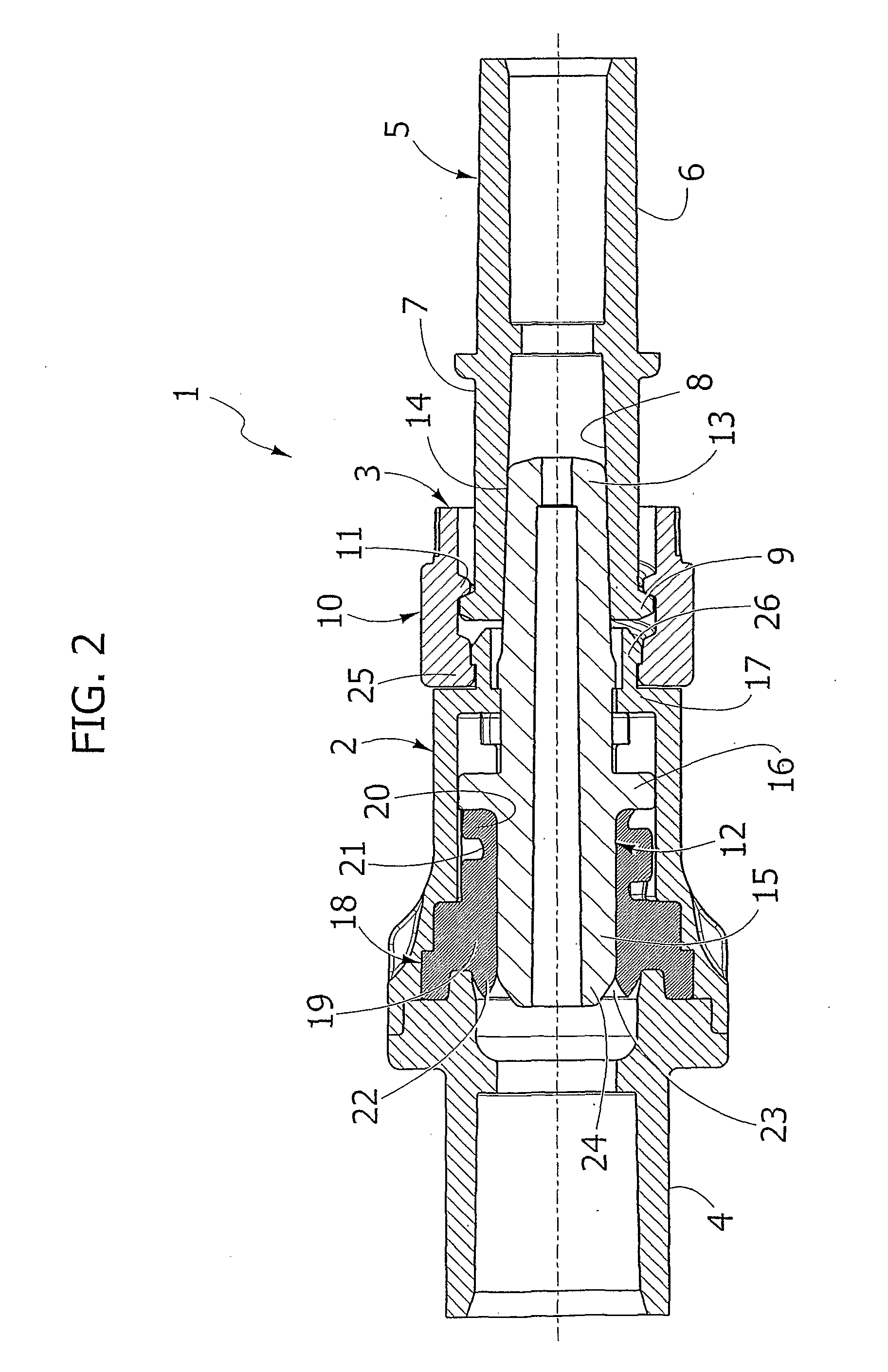
[0016]With initial reference to FIG. 1, designated as a whole by 1 is a valve connector according to the invention, basically comprising a tubular body 2 provided coaxially at its opposite ends with an inlet fitting 3 and an outlet fitting 4, and a tubular fitting 5. The components listed above of the medical connector 1 can all be made of moulded plastic material.

[0017]The tubular fitting 5 has a portion 6 designed to be connected to a first section of a medical line (for example, the tubing connected to a patient undergoing haemodialysis), and a second portion designated by 7, which can be coupled, in the way clarified in what follows, to the inlet fitting 3 of the tubular body 2.

[0018]The outlet fitting 4 of the tubular body 2 can in turn be connected to a second section of the medical line (for example, to the tubing of a dialyser).

[0019]The portion 7 of the tubular fitting 5 is shaped like a female luer-lock: it has, in a generally conventional way, an internal luer cone 8 and ...


PUM


Abstract

A valve connector for medical lines includes a tubular body having a male inlet fitting with external luer cone, which can be coupled to a female tubular fitting with internal luer cone, wherein the inlet fitting includes an internally threaded external tubular element for screwed engagement with the female fitting, and an internal tubular element that can be displaced axially from a retracted position of closing to an advanced position of opening of the valve means that control the passage of flow through the connector. The internally threaded external tubular element is free to turn, and the arrangement is such that, when it is screwed off the female fitting and the passage of flow is closed by the valve means, the external luer cone and the internal luer cone remain axially coupled to one another by friction.

Description

FIELD OF THE INVENTION[0001]The present invention relates in general to connectors for medical lines, for example for haemodialysis.[0002]More in particular, the invention relates to a valve connector of the type comprising a tubular body having a male inlet fitting with external luer cone, which can be coupled axially by friction within a female fitting with internal luer cone that is to be connected to a first section of the line (for example, a tubing connected to a patient undergoing dialysis). The tubular body has an outlet fitting designed to be connected to a second section of the line (for example, the tubing of a dialyser), and valve means for controlling the passage of flow between the inlet and outlet fittings.STATE OF THE PRIOR ART[0003]A valve connector of the above sort is described and illustrated in the European patent application No. EP-1747796A1 filed in the name of the present applicant. In said connector, the male inlet fitting of the tubular body comprises an in...

Claims


Application Information

Patent Timeline
IPC IPC(8): A61M39/26
CPCA61M39/10A61M2039/1072A61M2039/1033A61M39/26
Inventor GUALA, GIANNI
Owner IND BORLA
Learn More