Catheter with customizable connector

a catheter and connector technology, applied in the field of catheters, can solve the problems of high production cost, difficult to customize, and difficult to use, and achieve the effect of improving the service life of the catheter, improving the service life and improving the service li

a catheter and connector technology, applied in the field of catheters, can solve the problems of high production cost, difficult to customize, and difficult to use, and achieve the effect of improving the service life of the catheter, improving the service life and improving the service li

US20110060317A1Active Publication Date: 2011-03-10ASTRA TECH SE

Image

  • Catheter with customizable connector
  • Catheter with customizable connector
  • Catheter with customizable connector

Examples


Embodiment Construction

[0035]In the following detailed description preferred embodiments of the invention will be described. However, it is to be understood that features of the different embodiments are exchangeable between the embodiments and may be combined in different ways, unless anything else is specifically indicated. It may also be noted that, for the sake of clarity, the dimensions of certain components illustrated in the drawings may differ from the corresponding dimensions in real-life implementations of the invention, e.g. the length of the catheter, etc.

[0036]Catheters may be used for many different purposes, and for insertion into various types of body-cavities. However, the following discussion is in particular concerned with the preferred field of use, hydrophilic urinary catheters, even though the invention is not limited to this particular type of catheters.

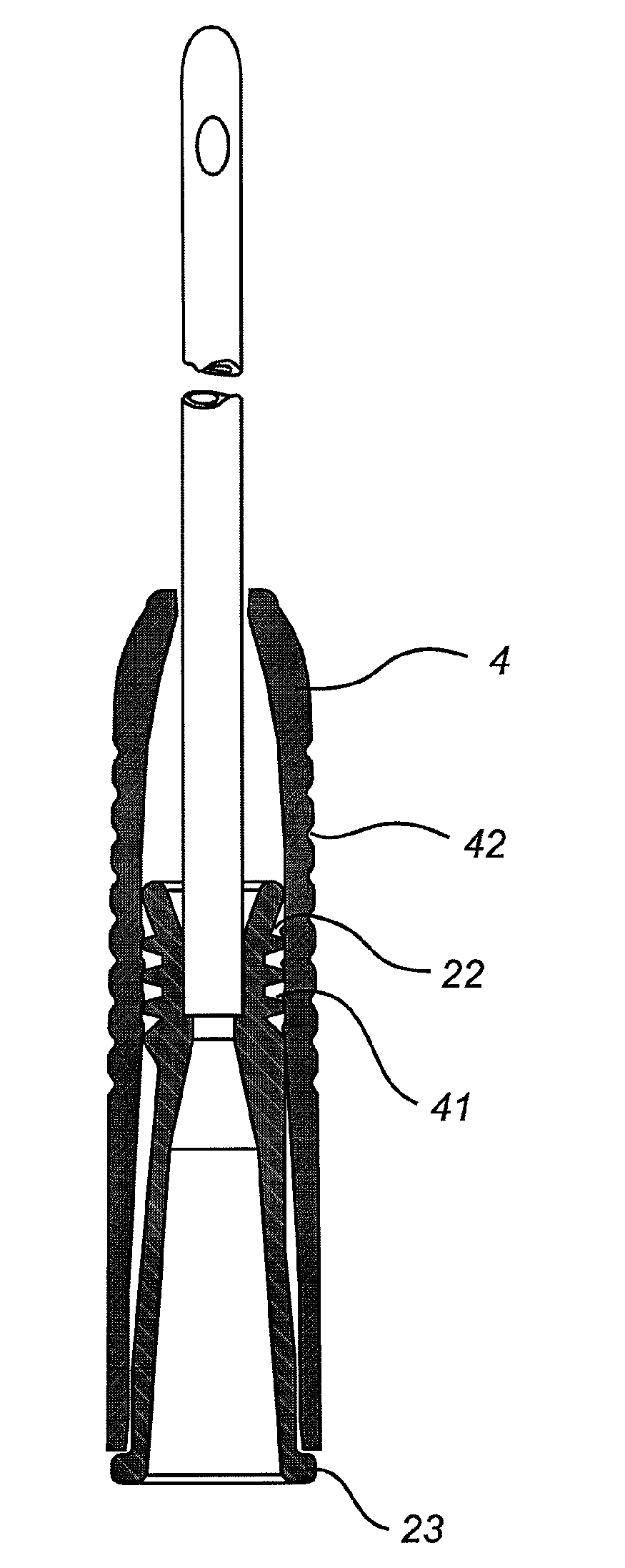
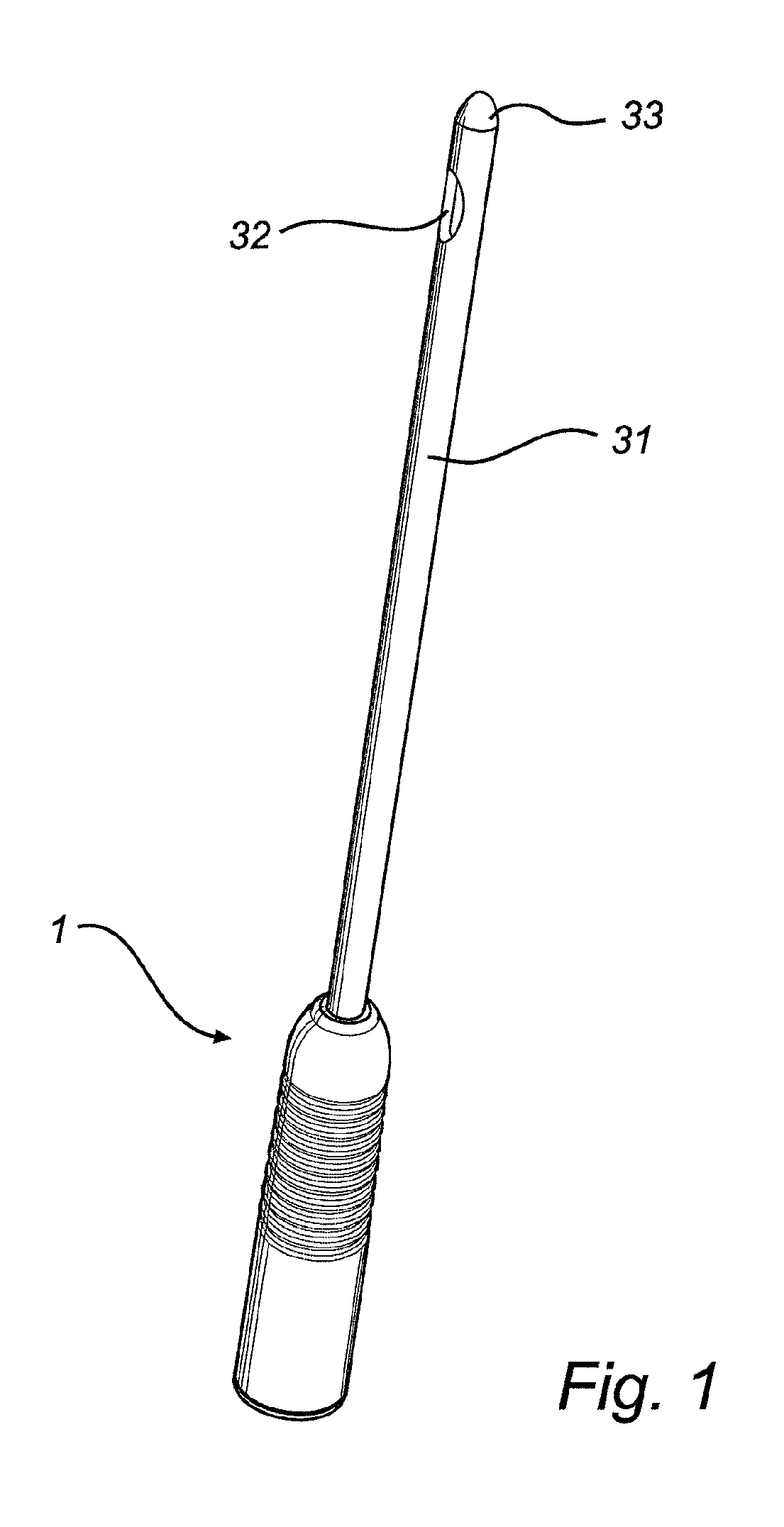
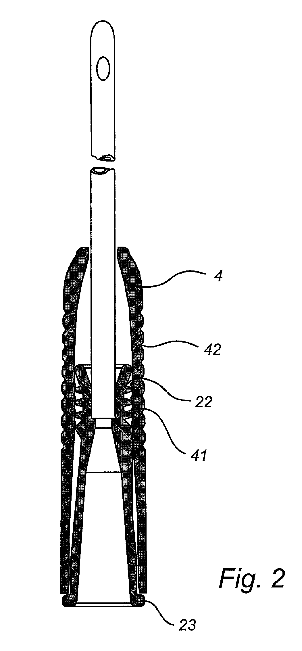
[0037]A catheter 1 as illustrated in the drawings, e.g. in FIG. 3, comprises a flared rearward portion, forming a flared connector ...


PUM

PropertyMeasurementUnit
Lengthaaaaaaaaaa
Lengthaaaaaaaaaa
Fractionaaaaaaaaaa

Abstract

A catheter, and preferably a urinary catheter, is disclosed, comprising an elongate shaft with a catheter insertion end and a flared connector connected to the elongated shaft opposite to the catheter insertion end. The flared connector forms a catheter connector end. Further, a gripping sleeve is fixedly connected to the flared connector, and arranged to enclose at leat part of, and preferably essentially the whole, flared connector, apart from the catheter connector end. Hereby, a standard catheter can easily be customized for various use situations and users with different needs, in terms of e.g. gripping and manipulation possibilities. A method for producing such a customized catheter is also disclosed.

Description

TECHNICAL FIELD OF THE INVENTION[0001]The present invention relates to a catheter, such as urinary catheters, and in particular to catheters of a relatively short length, such as female catheters.BACKGROUND[0002]The present invention relates to a catheter for draining bodily fluids, e.g. from the bladder. Urinary catheters are e.g. used by a large group of persons for intermittent catheterization, which is a daily-life procedure, taking place several times a day. Typically catheters for intermittent catheterization are used by patients suffering from urinary incontinence or by disabled individuals like para- or tetraplegics. Using an intermittent catheter, the bladder may be drained through a natural or artificial urethra. Many catheters for intermittent catheterization are provided with a hydrophilic coating or the like, providing a smooth and slippery surface for safe and comfortable insertion in the urinary canal.[0003]To this end, catheters should preferably be designed to enabl...

Claims


Application Information

Patent Timeline
10 Mar 2011
Publication
US20110060317A1
IPC
A61M27/00; B23P17/04
CPC
A61M25/0009; A61M25/0017; A61M25/0097; Y10T29/49826; A61M2025/0046; A61M2025/0681; A61M25/0111; A61M25/0014
Inventors
FROJD, GORAN