Exhaust gas treatment system

a gas treatment system and exhaust gas technology, applied in the direction of exhaust treatment electric control, machines/engines, mechanical equipment, etc., can solve the problems of increasing the size of the system, shortening the time it takes to start nox reduction, and increasing the entire length of the exhaust passag

Inactive Publication Date: 2011-03-17
TOYOTA IND CORP
View PDF0 Cites 71 Cited by
  • Summary
  • Abstract
  • Description
  • Claims
  • Application Information

AI Technical Summary

Benefits of technology

In accordance with an aspect of the present invention, an exhaust gas treatment system includes an exhaust passage through which exhaust gas from an internal combustion engine is allowed to flow, a selective catalytic reduction catalyst provided in the exhaust passage, a mixing chamber provided upstream of the selective catalytic reduction catalyst in th...

Problems solved by technology

In the system, use of combustion heat produced by the burner shortens the time it takes to activate the SCR catalyst after a cold start of the engine, resulting in shortening of the time it takes to start NOx reduction.
Thus, the combustion s...

Method used


Image

  • Exhaust gas treatment system
  • Exhaust gas treatment system
  • Exhaust gas treatment system

Examples


first embodiment

The exhaust gas treatment system 10 offers the following advantages.

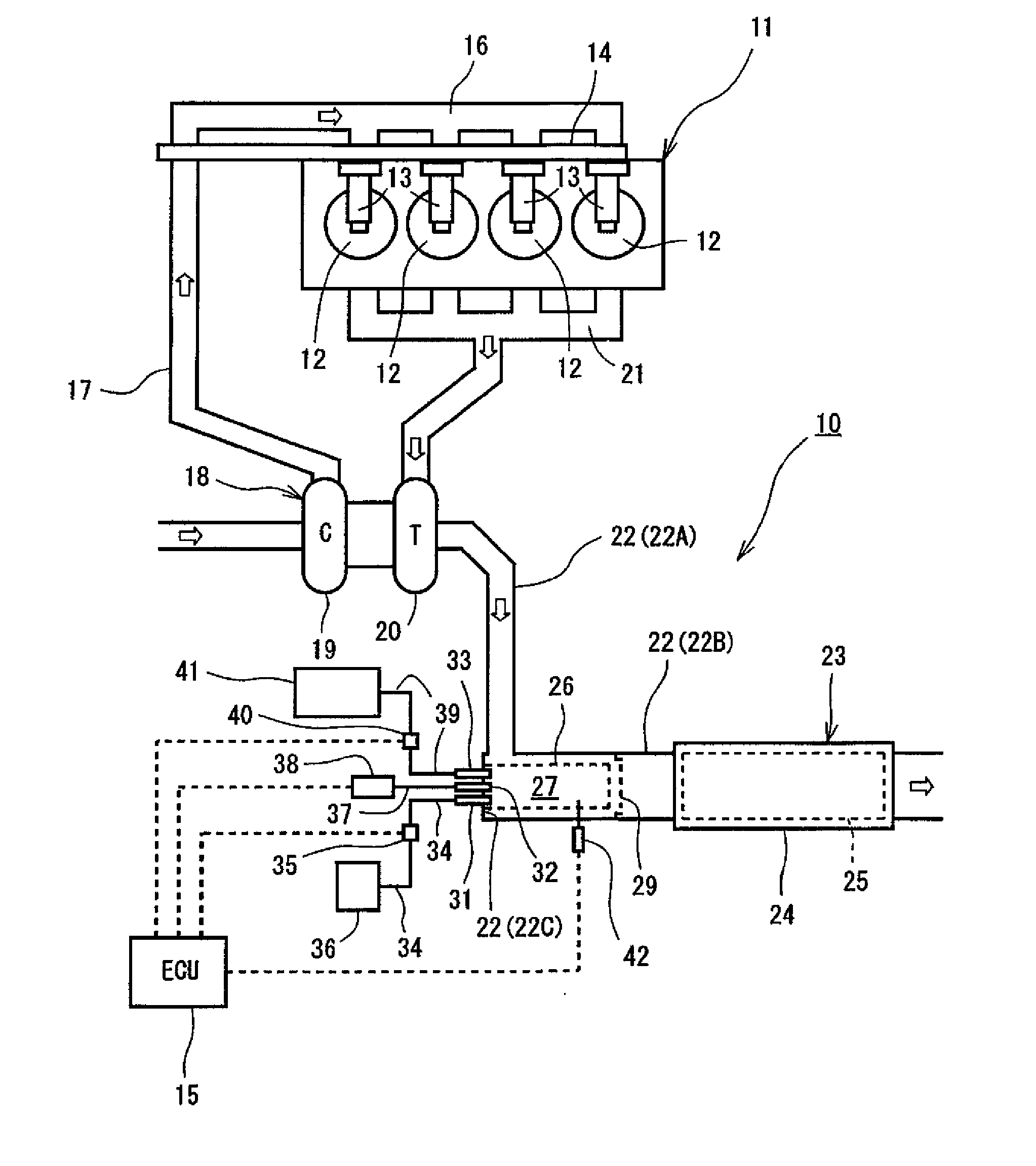
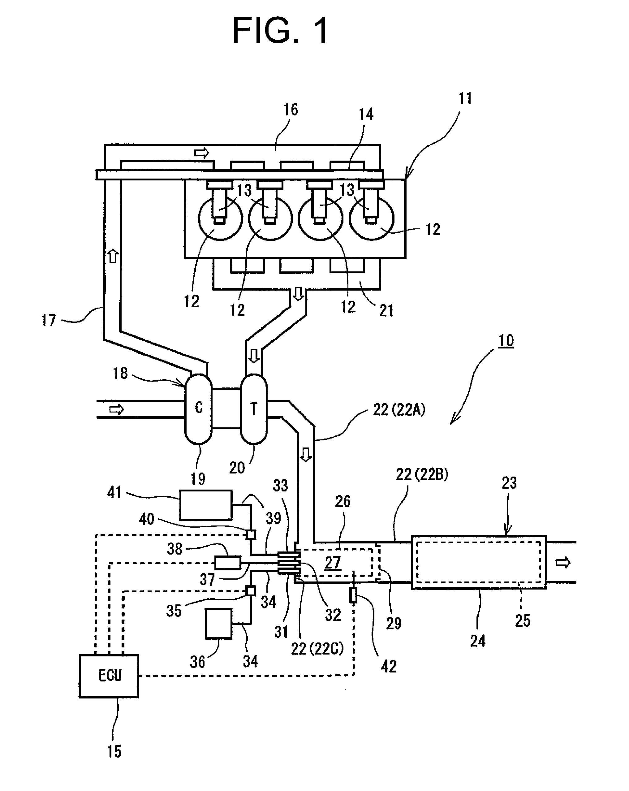
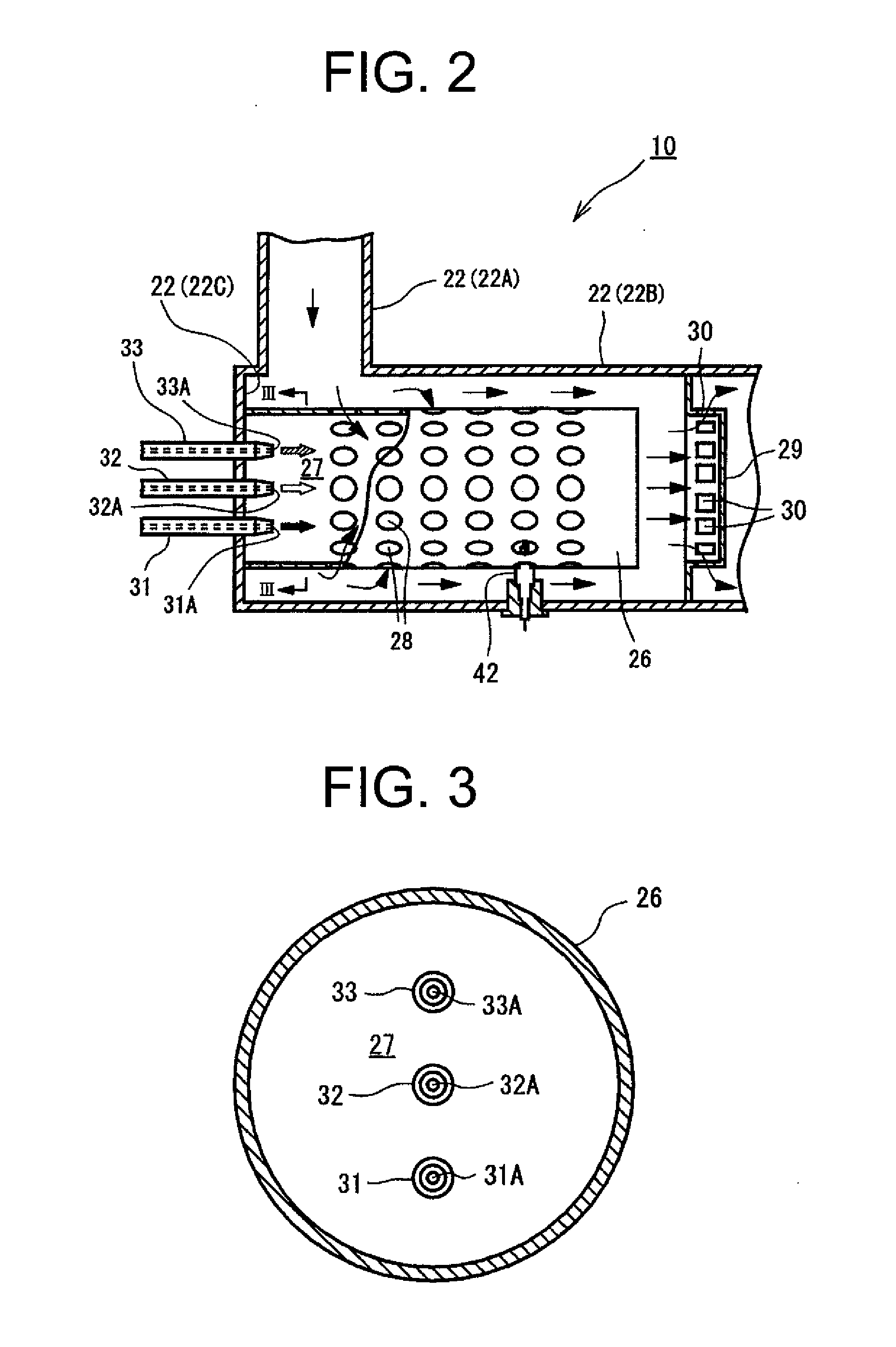
(1) Since fuel, air and urea water are injected into the mixing chamber 27, the injected fuel is combusted in the mixing chamber 27 to produce flame, and the combustion gas is mixed with the injected urea water. The heat of the combustion gas accelerates the hydrolysis of urea water into ammonia in the exhaust passage 22. The mixing chamber 27 formed in the exhaust passage 22 is used not only for combustion of fuel but also for mixing of combustion gas and urea water, which allows shortening of the entire length of the exhaust passage 22 and also allows uniform mixing of combustion gas and urea water.

(2) The air injection valve 32 is located between the fuel injection valve 31 and the urea water injection valve 33 so that the urea water injection valve 33 is spaced apart from the fuel injection valve 31 and located adjacent to the air injection valve 32. This allows cooling of the urea water injection valve 33 by i...

second embodiment

wherein the fuel injection valve, the air injection valve and the urea water injection valve are integrated in the multiple valve unit 51, the number of parts of the system can be reduced, and such injection valves can be provided at a time so as to be directed toward the mixing chamber 27. Further, the air passage 53 is located between the fuel passage 52 and the urea water passage 54 so that the urea water passage 54 is spaced apart from and located radially outward of and the fuel passage 52. In this case, the injected air prevents the urea water passage 54 from receiving heat directly from the fuel passage 52, thereby preventing overheating of the urea water passage 54.

The above embodiments may be modified in various ways as exemplified below.

An oxidation catalyst may be provided downstream of the SCR catalyst 23 in the exhaust passage 22 so as to remove the excessive ammonia produced from urea water and the ammonia released from the SCR catalyst 23.

Although in the first and sec...


PUM


Abstract

An exhaust gas treatment system includes an exhaust passage through which exhaust gas from an internal combustion engine is allowed to flow, a selective catalytic reduction catalyst provided in the exhaust passage, a mixing chamber provided upstream of the selective catalytic reduction catalyst in the exhaust passage as viewed in the direction of exhaust gas flow, a fuel injection valve for injection of fuel, an air injection valve for injection of air, and a urea water injection valve for injection of urea water. The fuel injection valve, the air injection valve and the urea water injection valve each has an injection port directed to the mixing chamber.

Description

BACKGROUND OF THE INVENTIONThe present invention relates to an exhaust gas treatment system, and more particularly to an exhaust gas treatment system including an injection valve for injecting urea water into exhaust gas and a selective catalytic reduction catalyst.A conventional exhaust gas treatment system is disclosed in Japanese Unexamined Patent Application Publication No. 2009-68424. The system includes an exhaust passage through which engine exhaust gas flows, a diesel particulate filter (DPF) provided in the exhaust passage, a urea SCR catalyst located downstream of the DPF in the exhaust passage as viewed in the direction of exhaust gas flow, and an ammonia oxidation catalyst located downstream of the urea SCR catalyst. The system further includes an injection nozzle for supplying urea water into the exhaust passage and a burner for accelerating activation of the SCR catalyst. The injection nozzle is provided between the DPF and the urea SCR catalyst, and the burner is prov...

Claims


Application Information

Patent Timeline
IPC IPC(8): F01N9/00F01N3/10F01N3/035F01N3/023F01N1/00
CPCF01N3/035F01N13/0097F01N3/2066F01N3/2892F01N3/30F01N3/36F01N9/002F01N2240/20F01N2250/02F01N2470/02F01N2610/02F01N2610/03F01N2610/08F01N2610/1453Y02T10/47Y02T10/24F01N3/0821Y02T10/12Y02T10/40
Inventor NORITAKE, KAZUTO
Owner TOYOTA IND CORP
Why Eureka
Try Eureka