Split-Type Valve Seat For A Faucet

Inactive Publication Date: 2011-03-17
XIAMEN LOTA INT CO LTD
View PDF38 Cites 5 Cited by
  • Summary
  • Abstract
  • Description
  • Claims
  • Application Information

AI Technical Summary

Benefits of technology

[0007]The inventive split-type valve seat for a faucet includes a plastic valve seat body and a metal cover. It features an environmentally friendly construction, light weight and low materials cost. Since

Problems solved by technology

If the strength of the valve seat is inadequate, the valve seat is prone to break in the process of installation and usage.
However, the cost of using true copper ma

Method used


Image

  • Split-Type Valve Seat For A Faucet
  • Split-Type Valve Seat For A Faucet
  • Split-Type Valve Seat For A Faucet

Examples


Example

[0015]The components in the drawings are not necessarily to scale, emphasis instead being placed upon clearly illustrating the principles of the present invention.

DETAILED DESCRIPTION

[0016]While this invention is susceptible of embodiments in many different forms, there is shown in the drawings and will herein be described in detail preferred embodiments of the invention. The present disclosure is to be considered as an exemplification of the principles of the invention. The disclosure is not intended to limit the broad aspect of the invention to the embodiments illustrated.

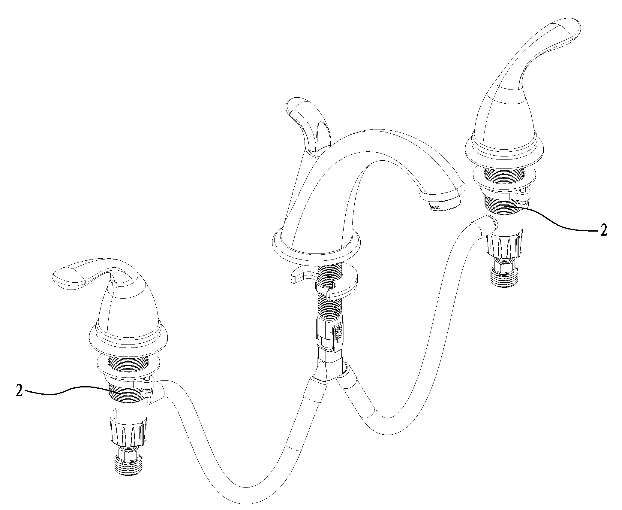
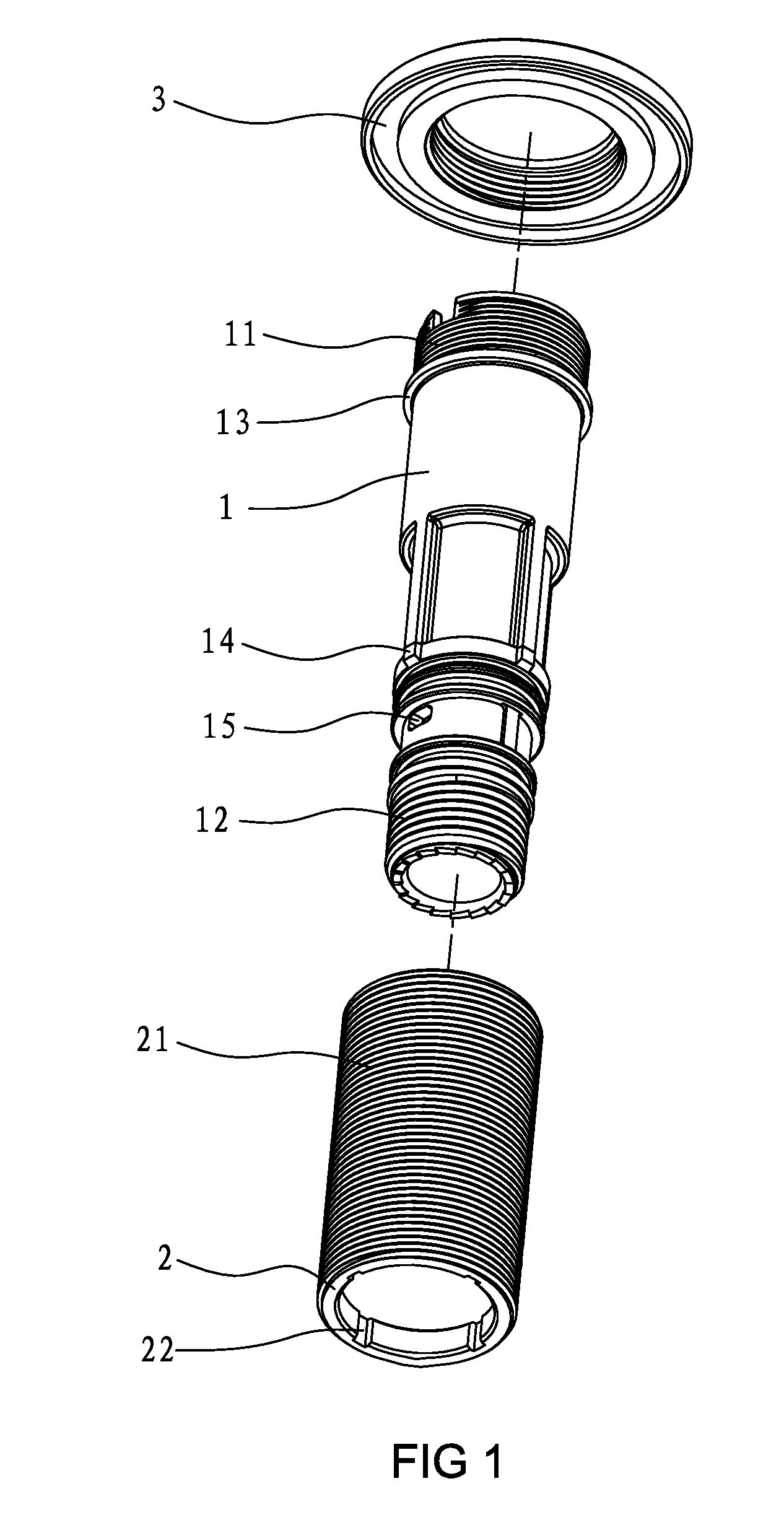
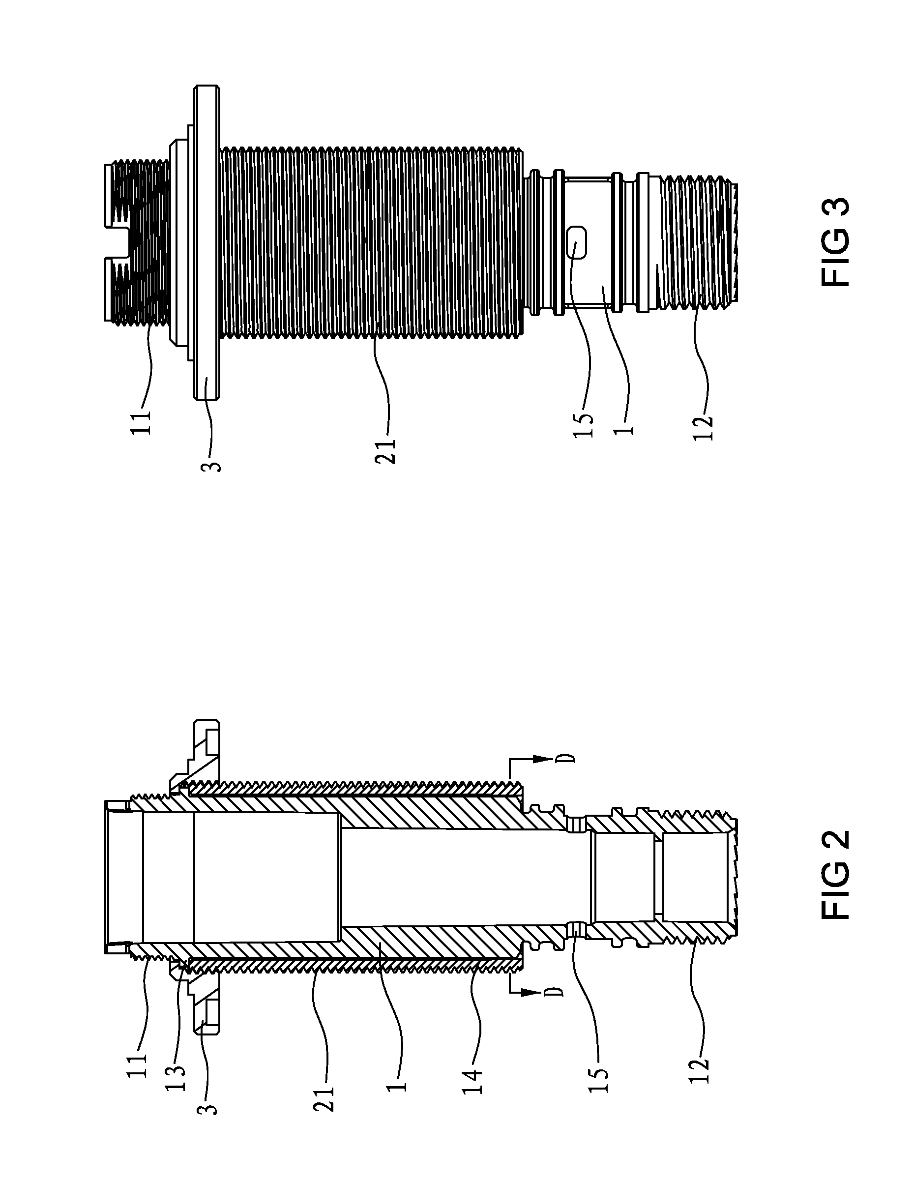
[0017]As seen in FIGS. 1, 3 and 4, the inventive split-type valve seat for a faucet includes a one-piece plastic valve seat body 1, a metal cover 2 and a flange 3. The valve seat body 1 is made of plastic, to be of one-piece construction. The two ends of the plastic valve seat body 1 separately include a threaded portion 11 and 12. The upper threaded portion 11 is connected to a fixed block 8 so that the water co...


PUM


Abstract

The inventive valve seat for a faucet includes a one-piece plastic valve seat body, a metal cover and a flange. The metal cover is set outside the valve seat body and is fixed to the valve seat body by the flange. The valve seat is environmentally friendly, and of light weight and low materials cost. Since the metal cover has high strength and is combined with a plastic valve seat body, it can bear the substantial forces imposed upon the valve seat.

Description

TECHNICAL FIELD[0001]The present invention relates to a valve seat for a faucet, especially a split-type valve seat.BACKGROUND OF THE INVENTION[0002]The water control assembly of a faucet is typically fixed to a valve seat by a fixed block. The faucet handle only can control the water control assembly after the valve seat is fixed to the basin. Therefore, the valve seat bears all the force imparted upon the faucet cartridge. If the strength of the valve seat is inadequate, the valve seat is prone to break in the process of installation and usage. Therefore, the valve seat for a faucet is typically made by true copper materials and formed to be one-piece by casting and forging. The strength of such a valve seat is high. However, the cost of using true copper materials is high. Moreover, the copper valve seat also contains heavy metals, such as Pb and Cd. Harmful heavy metals (such as Pb and Cd) will be released into the water after long usage. These metals will pollute the water and ...

Claims


Application Information

Patent Timeline
IPC IPC(8): F16K11/00
CPCF16K19/006Y10T137/86815
Inventor YE, LIMINGCHEN, BENTAI
Owner XIAMEN LOTA INT CO LTD
Why Eureka
Try Eureka