

Component removal tool and method
a technology of component removal and tool, which is applied in the direction of manufacturing tools, machines/engines, wood splitting, etc., can solve the problems of inoperable damage to the strut or other parts of the ring strut ring, and the inability to remove fan inlet shroud fairings
- Summary
- Abstract
- Description
- Claims
- Application Information
AI Technical Summary
Problems solved by technology
Method used
Image

Examples
Embodiment Construction
The present invention relates to a component removal tool and method. More particularly, the present invention relates to a tool and method capable of removing a fan inlet shroud fairing from a strut of a ring strut ring while eliminating or minimizing damage to the strut. The tool and method are described with reference to a fan inlet shroud fairing and a strut in gas turbine engines. However, similarly shaped components can also be separated according to the present invention.
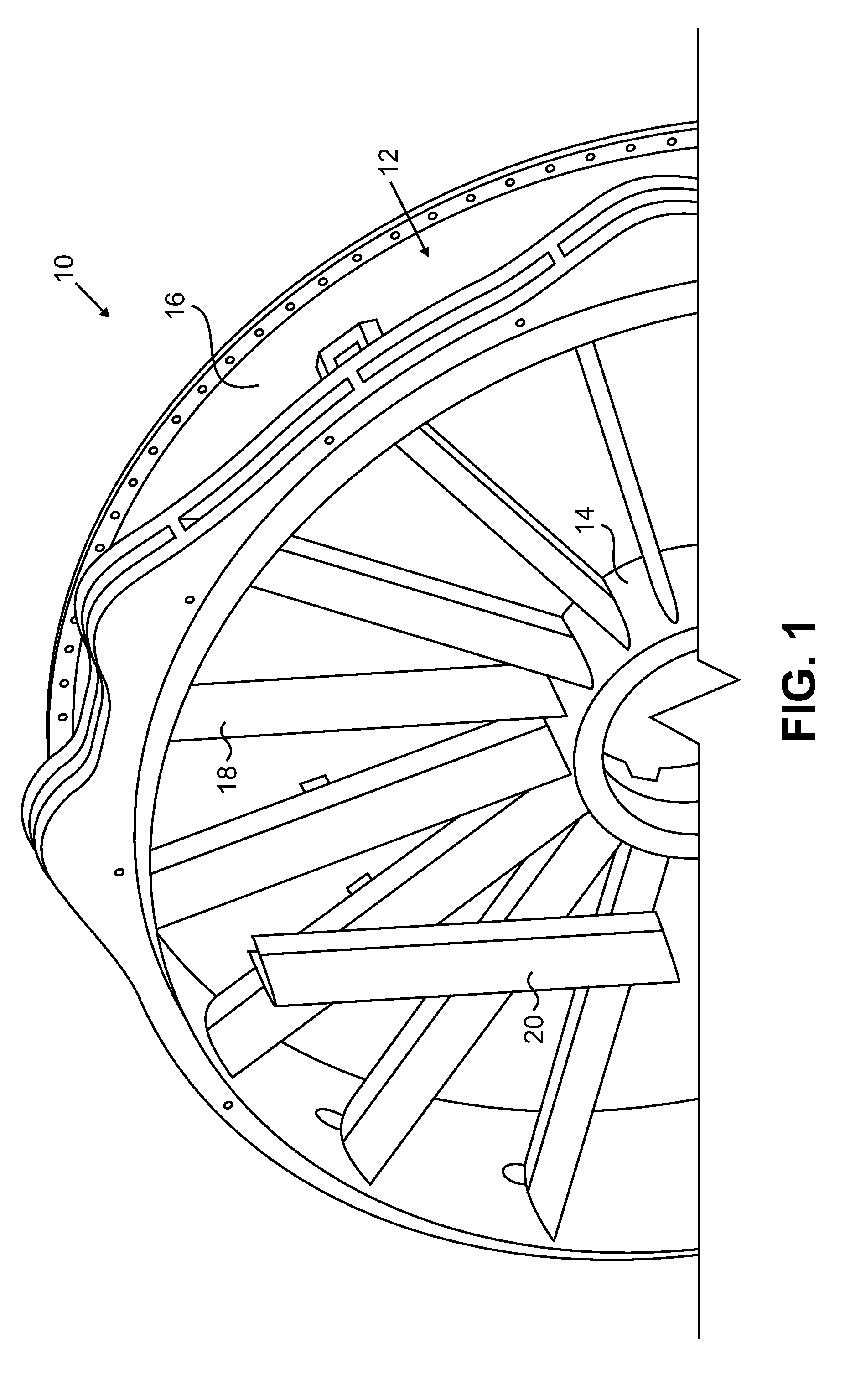
FIG. 1 illustrates part of a gas turbine fan inlet case 10 having a ring strut ring 12. Ring strut ring 12 includes inner ring 14, outer ring 16 and inner strut 18. Inner ring 14 and outer ring 16 are circular rings. Outer ring 16 is concentric with inner ring 14 and has a larger diameter than inner ring 14. Inner struts 18 extend between inner ring 14 and outer ring 16. For example, in one gas turbine fan inlet case 10, ring strut ring 12 contains seventeen inner struts 18. However, more or fewer inner strut...
PUM
 Abstract
Description
Claims
Application Information