Touch Pad Disc Jockey Controller

a disc jockey controller and touch pad technology, applied in the field of digital audio signal control and manipulation, can solve the problems of user rotatable discs being limited to rotary motion on the entire surface, unsuitable for portable applications, and bulky arrangements, etc., to achieve accurate and precise control of audio parameters including scratch effects, portable, and improved control and display devices for djs

Active Publication Date: 2011-03-17
INMUSIC BRANDS
View PDF27 Cites 17 Cited by
  • Summary
  • Abstract
  • Description
  • Claims
  • Application Information

AI Technical Summary

Benefits of technology

It is therefore an object of the present invention to provide an improved control and display device for DJs that is portable, durable, and provides accurate and precise control of audio parameters including a scratch effect.

Problems solved by technology

These arrangements tend to be bulky, heavy, expensive, and complex and therefore are not ideal for portable applications.
In addition, the user rotatable disc is limited to rotary motion on the entire surface and can only be used for one function at a time.
As with the scratch effect controller, the user rotatable jog wheel is limited to rotary motion on the entire surface and can only be used for one function at a time.
Because there is a mechanical rotating jog wheel or platter, DJ CD players 200 with a user rotatable surface tend to have complex mechanical arrangements and tend to be bulky, heavy, expensive, and not ideal for portable applications.
These tend to be less accurate and more difficult to control, then the previously described controllers.
They also suffer from the same limitation of allowing only one function at a time on the user manipulable disc.
Creating a scratch effect with a mouse is not desirable because the act of grasping the mouse is cumbersome and hinders the DJ's performance.
The touch pad offers the advantage of potentially better control than the mouse but suffers several disadvantages: (1) only linear motion is possible, and (2) a standard touch pad can not provide direct visual feedback as to help the DJ refine their performance.
Because they tend to be small, performing an accurate scratch effect suitable for live performance by a professional DJ is not desirable.
However, none of the above mentioned devices solve the problem of portability, durability, and accuracy for creating scratch effects on a DJ control surface.

Method used


Image

  • Touch Pad Disc Jockey Controller
  • Touch Pad Disc Jockey Controller
  • Touch Pad Disc Jockey Controller

Examples


Embodiment Construction

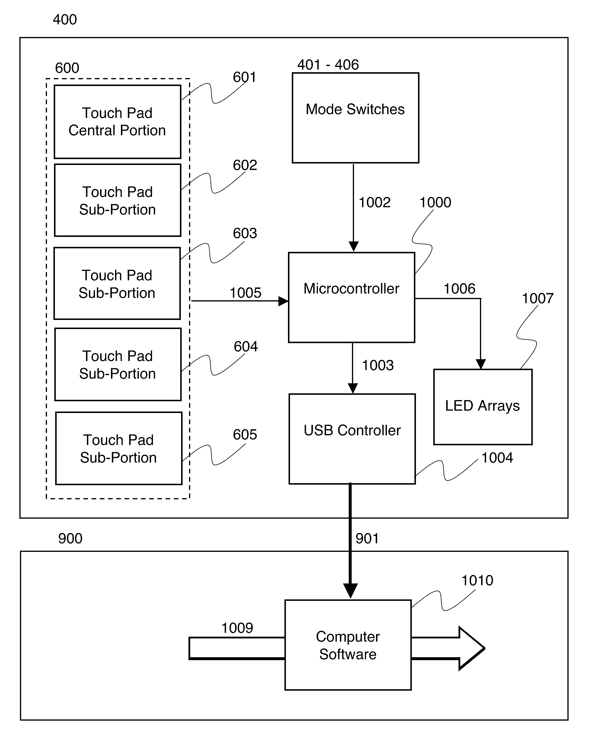
Referring now to the drawings in detail, wherein like numerals indicate like elements throughout the several views. FIG. 4 discloses an embodiment of the present invention. A self-contained DJ controller 400 has a substantially circumferential touch sensitive surface 410. The touch sensitive surface in the present embodiment is a capacitive touch sensor. Those skilled in the art will recognize that other touch pad technology may be substituted. The touch sensitive surface 410 is divided into a circumferential portion 421 and a central portion 422. The circumferential portion 421 is disposed to respond to circumferential or rotary motion imparted by the user. In this embodiment the central portion 422 is disposed to respond only to linear motion imparted by the user. This is accomplished by programming an internal processor 1000, typically a microcontroller, as shown in FIG. 10, within the DJ control device 400, to accept only vertical linear motion from the central portion 422. the ...


PUM


Abstract

The present invention pertains to the field of control and manipulation of a digital audio signal by a user manipulable touch sensitive control surface. The present invention is specifically applicable to user manipulation of digital audio signals by disc jockeys (DJs).
A touch sensitive surface substantially circumferential in shape is divided into two regions: an inner or central portion and an outer or circumferential portion. The inner portion responds to linear motion imparted by the user while the outer portion responds to circumferential motion. The linear motion imparted by the user in the central portion is used manipulate a digital audio data stream in order to impart a scratch effect.

Description

BACKGROUND OF THE INVENTION1. Field of the InventionThe present invention pertains to the field of control and manipulation of a digital audio signal by a user manipulable touch sensitive control surface. The present invention is specifically applicable to user manipulation of digital audio signals by disc jockeys (DJs).2. Description of the Prior ArtScratch effects controllers for live disc jockey musical performances (DJing) have become a popular replacement by DJs for conventional turntable and phonographic LP records for producing a “scratch effect” or to generally manipulate the speed and direction of music.The original “scratch effect” is a very specific sound produced when a DJ simultaneously performs two actions. The DJ rotationally manipulates a vinyl record on a phonographic turntable in a rapid forward and backward movement. While doing this, the DJ also modulates the sound from the turntable on a DJ audio mixer, by quickly moving the mixer's cross fader back and forth in...

Claims


Application Information

Patent Timeline
Patent Type & Authority Applications(United States)
IPC IPC(8): G06F3/041
CPCG10H1/0091G10H2210/241G10H2240/321G10H2240/285G10H2240/315G10H2220/161
Inventor MAZUR, JAMESGIBSON, BRIANLANGLOIS, DAMON
Owner INMUSIC BRANDS
Why Eureka
Try Eureka