Method and system for correction, measurement and display of images

a technology of image correction and image, applied in the field of backlit display systems, can solve the problems of significant differences in the approach to measuring ambient light from traditional single and multi-sensor methods, and achieve the effects of maximizing image quality, improving front sensor readings, and minimizing interferen

Inactive Publication Date: 2011-03-17
THE GSI GRP LLC
View PDF26 Cites 12 Cited by
  • Summary
  • Abstract
  • Description
  • Claims
  • Application Information

AI Technical Summary

Benefits of technology

[0008]One aspect of the invention relates to a system for displaying images for medical use. The system maintains the brightness level of the display at a fixed brightness in real time and measures the display's conformance to display standards such as DICOM. In one embodiment, the system uses three sensors to correct readings made at the edge of backlit displays. The sensors may be placed with one behind the center of the BLU, one on the edge of the front of the display, and a third sensor behind the BLU directly behind the front sensor. The placement of the front sensor minimizes interference with the active image and maximizes image quality. The invention is not dependent on this specific placement or number of sensors, but more generally with a sensor system to provide feedback to improve front sensor readings.

Problems solved by technology

This approach is significantly different from traditional single and multi-sensor methods for measuring ambient light.

Method used


Image

  • Method and system for correction, measurement and display of images
  • Method and system for correction, measurement and display of images
  • Method and system for correction, measurement and display of images

Examples


Embodiment Construction

[0028]The display system of this invention may be used in the area of medical systems which provide information and requires an accurate display of the image. In these medical systems, it is often important to verify conformance of the display function to industry standards, such as DICOM. The display function is the mapping of digital pixel values to display luminance. The standards such as DICOM prescribe a display function to maximize visible details in the medical image as well as provide a consistent image presentation when displayed on conformant monitors.

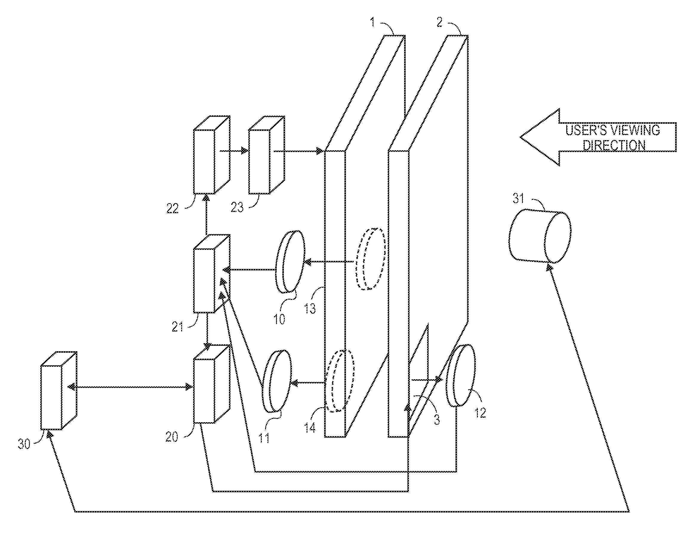
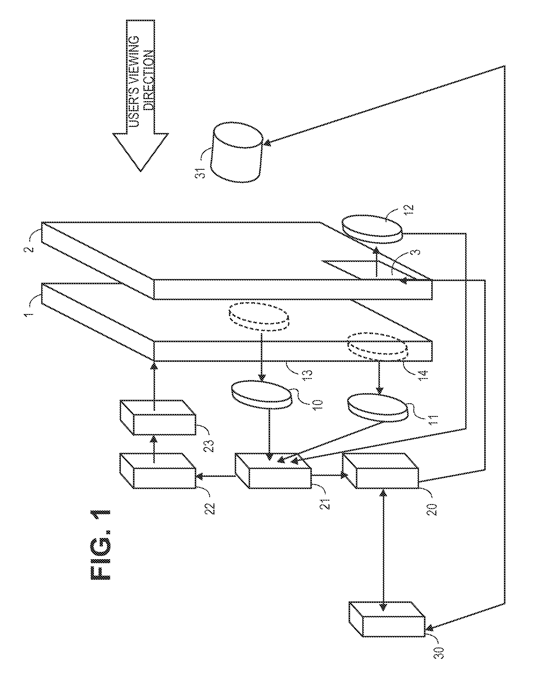
[0029]FIG. 1 illustrates one embodiment of the display system. In FIG. 1, the display device has a LCD active area 2 and test pattern area 3. The test pattern area 3 may be either a dedicated area of the display device outside the active area or part of the active area of the display. A BLU control unit, including control logic 22 and control hardware 23, is capable of driving the overall brightness of the display. A sensor 1...


PUM


Abstract

One aspect of the invention is a system for displaying images. A display device comprises a back light unit and a first aperture and a second aperture in the back light unit. The display device also comprises a first sensor, a second sensor, and a third sensor. The first sensor is configured to measure a first brightness value of the back light unit through the first aperture. The second sensor is configured to measure a second brightness value of the back light unit through the second aperture. The third sensor is configured to measure a third brightness value from a front portion of the display device.

Description

CROSS REFERENCE TO RELATED APPLICATIONS[0001]This application claims priority under 35 U.S.C. §119 to U.S. Appl. No. 61 / 242,744, filed Sep. 15, 2009, the disclosure of which is incorporated herein by reference.FIELD OF THE INVENTION[0002]The present invention relates generally to backlit display systems, such as liquid crystal displays (LCDs).INCORPORATION BY REFERENCE[0003]All publications and patent applications mentioned in this specification are herein incorporated by reference to the same extent as if each individual publication or patent application was specifically and individually indicated to be incorporated by reference.BACKGROUND OF THE INVENTION[0004]There are several methods of controlling the back light brightness and a similar number of methods of measuring the conformance of the display to a particular response curve, such as DICOM Grayscale Display Function (GSDF). Each of these methods has limitations on the ability to control the brightness accurately and report t...

Claims


Application Information

Patent Timeline
Patent Type & Authority Applications(United States)
IPC IPC(8): G09G5/10G09G3/36
CPCG09G3/006G09G3/3406G09G2360/145G09G2320/0626G09G2320/0693G09G2320/029
Inventor KNICELY, WENDELLHARRIS, EUGENE R.STEVEN, PETER M.
Owner THE GSI GRP LLC
Why Eureka
Try Eureka