
Frequency shifting based interference cancellation device and method

Inactive Publication Date: 2011-03-17
UBIDYNE
View PDF16 Cites 34 Cited by
  • Summary
  • Abstract
  • Description
  • Claims
  • Application Information

AI Technical Summary

Benefits of technology

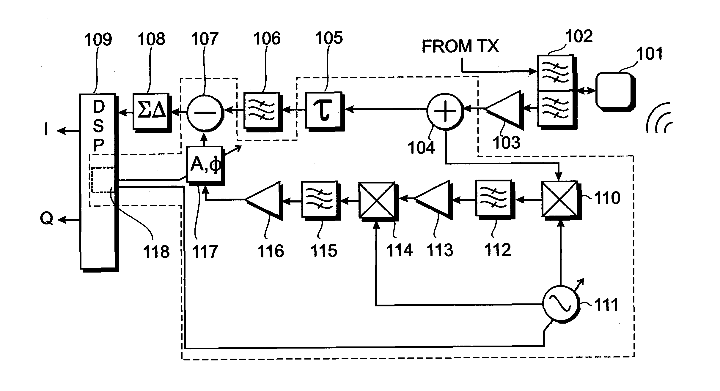
[0010]The interference cancellation device of the disclosure comprises an input, a first frequency shifter, a bandpass filter, and a signal combiner. The input is adapted to receive a disturbed signal which includes an interference signal. The first frequency shifter shifts the disturbed signal from an original frequency range to a filtering frequency range, resulting in a frequency-shifted signal. The band pass filter filters the frequency-shifted signal, resulting in a cancellation signal. The band-pass filter has a filter bandwidth substantially equal to an expected bandwidth of the interference signal. The signal combiner combines the disturbed signal with the cancellation signal to substantially reduce the interference signal in the disturbed signal.
[0013]The first frequency shifter may be a mixer. A mixer usually mixes a mixer input signal with a local oscillator signal. Depending on the frequency of the local oscillator signal, the mixer input is shifted (actually “mirrored”) in the frequency domain. The frequency of the local oscillator signal can usually be adjusted relatively easily and accurately.
[0014]When there is a first frequency shifter and a second frequency shifter both of the first frequency shifter and the second frequency shifter may be mixers and the interference cancelation device may further comprise a local oscillator for supplying a local oscillator signal to the first frequency shifter and the second frequency shifter. The use of a single local oscillator serving both the first frequency shifter and the second frequency shifter reduces cost, size and weight of the interference cancelation device. Furthermore, it ensures that the cancelation signal is substantially exactly shifted back to the first frequency range.
[0025]The interference cancelation device may further comprise a cancelation signal splitter and additional signal combiners for combining the cancelation signal with other disturbed signals comprising similar or identical interference signals to substantially reduce the similar or identical interference signals in the other disturbed signals. If necessary, at least some of the additional signal combiners may be accompanied by gain controllers and / or phase controllers (possibly one gain controller and / or phase controller per additional signal combiner) so that the gain and phase of the cancelation signals in the additional signal combiners can be substantially matched to the interference signals that arrive at the respective additional signal combiners. The cancellation controller may provide individual control to each of the gain controllers and / or phase controllers accompanying the additional signal combiners.
[0026]The present disclosure further describes a method for interference cancelation on a disturbed signal comprising an interference signal. The disturbed signal is frequency shifted from an original frequency range to a filtering frequency range, resulting in a frequency-shifted signal. The frequency-shifted signal is band pass filtered, resulting in a cancelation signal, wherein a bandwidth of the band pass filtering substantially matches an expected bandwidth of the interference signal. The disturbed signal is then combined with the cancelation signal to substantially reduce the interference signal in the disturbed signal.
[0034]The method may further comprise combining the cancelation signal with other disturbed signals comprising similar or identical interference signals to substantially reduce the similar or identical interference signals in the other disturbed signals.

Problems solved by technology

Therefore, the proposed interference cancelation device is able to deal with in-band blocker signals or out-of-band blocker signals, whereas previous methods only dealt with one or more out-of-band blocker signals and cannot deal with in-band blocker signals which are buried in amongst one or more wanted signals.

Method used


Image

  • Frequency shifting based interference cancellation device and method
  • Frequency shifting based interference cancellation device and method
  • Frequency shifting based interference cancellation device and method

Examples


Embodiment Construction

[0046]The invention will now be described on the basis of the drawings. It will be understood that the embodiments and aspects of the invention described herein are only examples and do not limit the protective scope of the claims in any way. The invention is defined by the claims and their equivalents. It will be understood that a feature of one aspect can be combined with features of a different aspect or aspects.

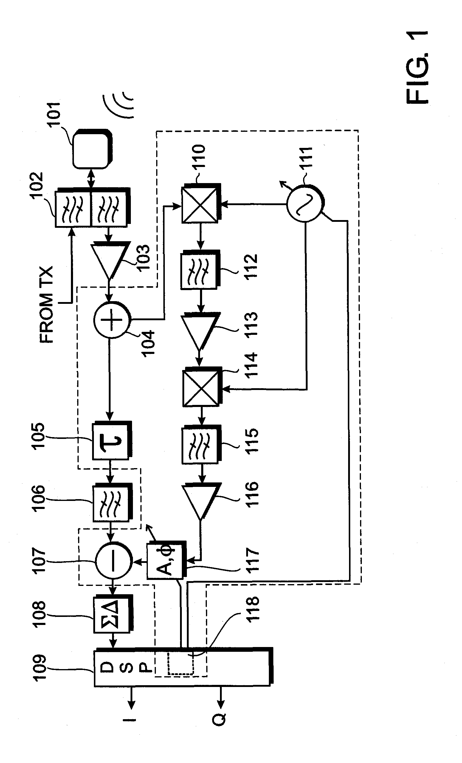
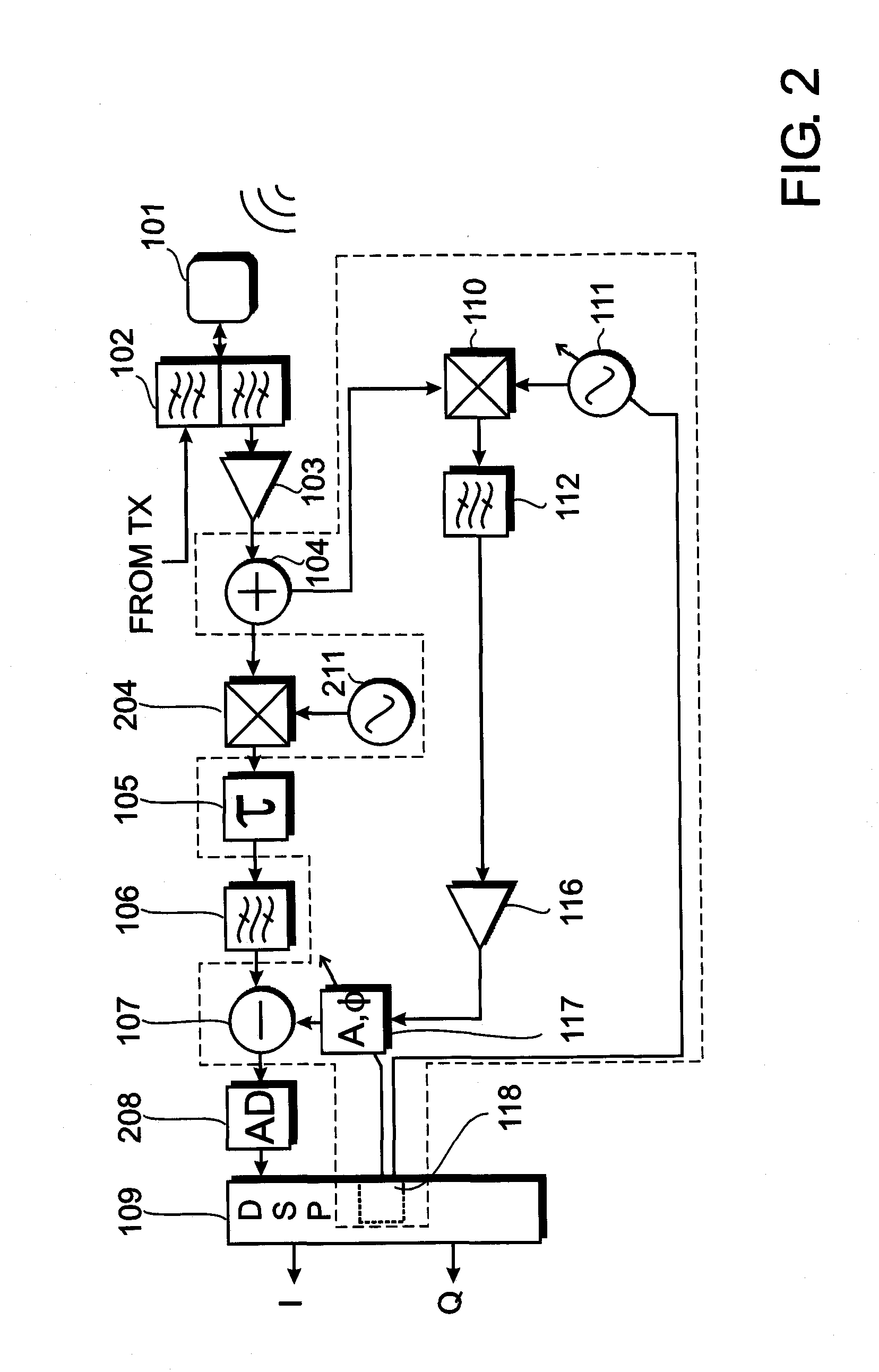
[0047]FIG. 1 shows a receiver arrangement or a receive path that may be used in a base-station of a mobile communications network. A signal from a remote transmitter is received at an antenna 101. The antenna 101 is connected to a duplex filter 102 that separates a transmission path from the receive path in the frequency domain. Instead of the duplex filter 102, other techniques may be used, such as a circulator or time multiplexing. The signal arriving from the transmission path is illustrated as an input to an upper part of the duplex filter 102. A lower part of the dup...


PUM


Abstract

An interference cancellation device comprises an input for a disturbed signal, a first frequency shifter, a bandpass filter, and a signal combiner. The first frequency shifter shifts the disturbed signal from an original frequency range to a filtering frequency range. The frequency-shifted signal is filtered by the bandpass filter. The filtered signal is supplied to the signal combiner which combines the filtered signal with the disturbed signal to substantially reduce the interference signal that is present in the disturbed signal. A method for interference signal cancellation is also proposed. Furthermore, a computer program product with instructions for the manufacture and a computer program product enabling a processor to carry out the method for interference signal cancellation are also proposed.

Description

CROSS REFERENCE TO OTHER APPLICATIONS[0001]The present application is related to a patent application entitled “Mismatched delay based interference cancellation device and method” (Attorney Docket No. 4424-P04912US0) filed concurrently herewith. The entire disclosure of the foregoing application is incorporated herein by reference.FIELD OF THE INVENTION[0002]The field of the present invention relates to an interference cancellation device, for example for use in a receiver of a base transceiver station of a mobile communications network. The field of the present invention further relates to a method for interference cancellation on a disturbed signal comprising an interference signal. The field of the present invention also relates to a computer program product enabling a foundry to carry out the manufacture of an interference cancellation device, and to a computer program product enabling a processor to carry out the method for interference cancellation.BACKGROUND OF THE INVENTION[...

Claims


Application Information

Patent Timeline
IPC IPC(8): H04B1/10
CPCH04B1/126
Inventor KENINGTON, PETER
Owner UBIDYNE
Learn More