Control device for fluid loading and/or unloading system

a control device and fluid technology, applied in adaptive control, passenger handling apparatus, instruments, etc., can solve problems such as difficult implementation of control devices, coupling damage, coupling strike risk,

Inactive Publication Date: 2011-03-17
FMC TECH SA
View PDF18 Cites 13 Cited by
  • Summary
  • Abstract
  • Description
  • Claims
  • Application Information

AI Technical Summary

Benefits of technology

[0045]the means for providing information on the positioning of the target duct includes a device of a system for global positioning in particular of GPS type, making it possible to give an absolute position of the target duct, the calculating means being adapted to calculate, on the basis of the information on absolute positioning of the target duct, the relative positioning of the coupling relative to the target duct;
[0046]the means for providing information on the positioning of the of the coupling includes a device of a system for global positioning, in particular of GPS type, making it possible to give an absolute position of the coupling, the calculating means being adapted to calculate, on the basis of the information on absolute positioning of the coupling and of the target duct, the relative positioning of the coupling relative to the target duct;

Problems solved by technology

These control devices are difficult to implement, in that the operator must know the functioning and kinematics of the marine loading system perfectly Furthermore, he must compensate for the movements of the ship, in particular in the case of rough sea.
This increases the risk of the coupling striking against obstacles or against the target duct, which may damage the seals of the coupling.

Method used


Image

  • Control device for fluid loading and/or unloading system
  • Control device for fluid loading and/or unloading system
  • Control device for fluid loading and/or unloading system

Examples


Embodiment Construction

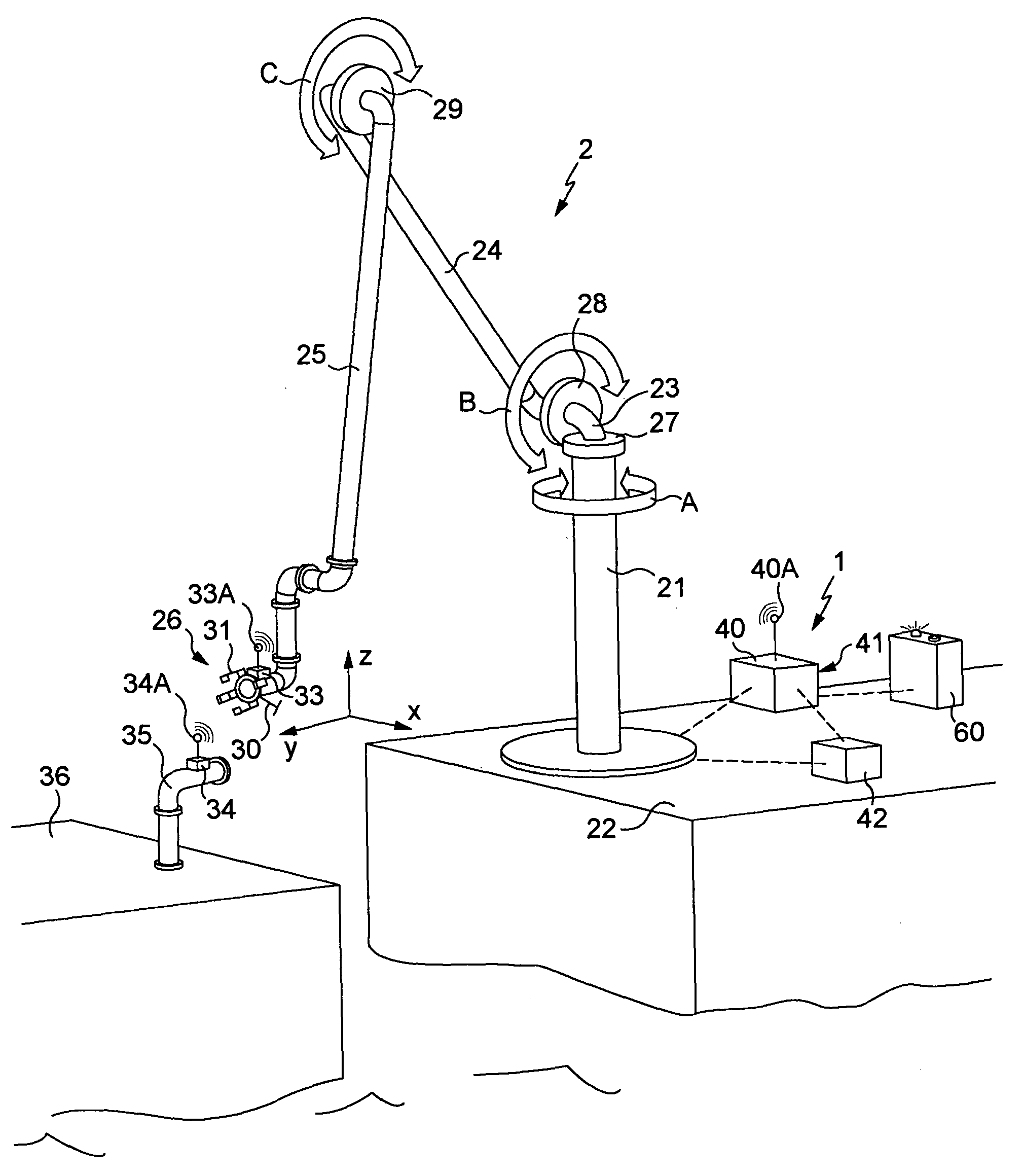
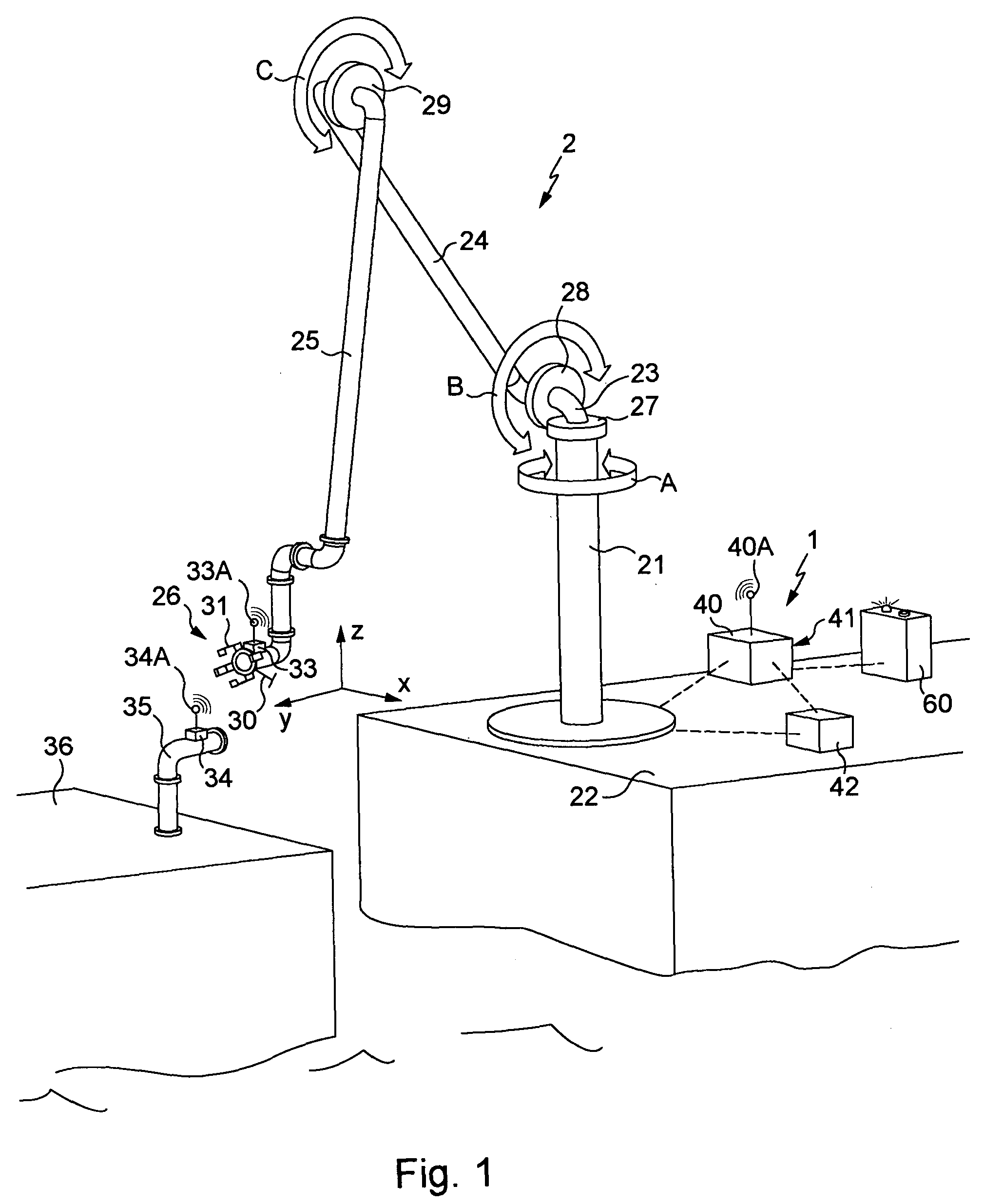
[0081]FIG. 1 is a very diagrammatic representation of a loading arm 2 equipped with a control device 1 according to the invention. The representation of the loading arm here is very simplified, and it should be recalled in this connection that the control device according to the invention adapts to any type of marine loading system, in particular to the loading systems described above.

[0082]The loading arm of FIG. 1 comprises a base 21 connected to a fluid tank which is located below the surface 22 on which the base is fixed. In the present case it is a quay, but in a variant it is a ship. At the apex of the base there is rotatably articulated a bent tube 23, on which is articulated in turn a first tube referred to as inner tube 24 which is articulated at its opposite end with a second tube referred to as outer tube 25. The end of the outer tube carries a coupling 26 adapted to be connected to a target duct 35, disposed in the present example on a ship 36 represented very diagrammat...


PUM


Abstract

A control device (1) for the movement and positioning of a coupling (26) for a marine loading system (2), comprising at least one fluid transfer line having a line end fixed to a base (21), and a moveable line end provided with a coupling (26) adapted for connection to a target duct (35), the device comprising at least three actuators (27, 28, 29) each for controlling the movement of the system in a degree of freedom, and a command interface (60) and at least one member of the group coupling/target duct or a member that is fixed relative to one at least of the members of the group coupling/target duct comprises at least one means for providing information on positioning of the coupling (33, 34), and the device furthermore comprises calculating means (41) adapted to: calculate the relative positioning of the coupling directly relative to the target duct according to the information provided by the positioning information means of the coupling, calculate control instructions to give to each of the actuators such that their combined movements result in a movement of the coupling aimed at bringing the coupling closer to the target duct, apply said control instructions to bring the coupling closer to the target duct, reiterate the three preceding steps until the coupling is presented in front of the target duct in a position for connection.

Description

BACKGROUND OF THE INVENTION[0001]The present invention generally relates to systems for loading and / or unloading fluids for ships, commonly referred to as marine loading systems. These systems are used to transfer a fluid product between a ship and a quay or between two ships.[0002]Fluid product is understood to mean a liquid or gaseous product.[0003]More particularly, the present invention concerns the devices for controlling movement, positioning and connection of such loading and / or unloading systems.[0004]Generally, marine loading systems have a fluid transfer line end that is fixed to a base and connected to a tank of fluid to be transferred, and an opposite line end that is moveable and provided with a coupling adapted for connecting to a target duct, itself connected to a fluid tank.[0005]Two families of fluid loading systems for ships are known, which are distinguished by their structure: systems for transfer by rigid pipes and systems for transfer by flexible pipes.[0006]In...

Claims


Application Information

Patent Timeline
Patent Type & Authority Applications(United States)
IPC IPC(8): G05B15/02B67D9/02
CPCB67D9/02B63B27/24B63B27/25B63B27/34B67D2210/00141B67D2210/00047
Inventor LE DEVEHAT, RENAUDSYLARD, NICOLAS
Owner FMC TECH SA
Why Eureka
Try Eureka