
Data transfer apparatus, data transfer device, and data transfer method in a data transfer device

data transfer technology, applied in the field of data transfer apparatus, data transfer device, and data transfer method in a data transfer device, can solve the problems of increasing the delay time required for transfer, reducing the data transfer rate, and reducing the number of data transfer packets

Inactive Publication Date: 2011-03-17
RICOH KK
View PDF7 Cites 21 Cited by
  • Summary
  • Abstract
  • Description
  • Claims
  • Application Information

AI Technical Summary

Benefits of technology

[0025]It is an object of the present invention to at least partially solve the problems in the conventional technology.

Problems solved by technology

As compared to the typical parallel data transmission technology, the serial data transmission technology is operated on a wider data transfer bandwidth but at the same time has an increased delay time required for transfer.
Hence, in the case of long-distance transmission using a cable, if a device having no consideration given to cable connection is connected as it is; then the increased delay time due to the cable connection causes a delay in receiving acknowledgment (ACK) packets as the response from addressee devices.
That leads to the occurrence of timeouts thereby causing to decline in the data transfer rate.
In a device having no consideration given to cable connection, the short delay time leads to a decrease in the installation cost.
For that reason, longer the cable length, longer is the response wait time and larger is the decrease in the data transfer efficiency.
However, in a conventional apparatus performing the high-speed serial transmission using a cable, the abovementioned measure is nothing more than inserting a temporary buffer in the device or on the transmission path.
The manufacturing of a device with a changed buffer size is an expensive task.
Moreover, if the addressee device to be connected includes only small buffers, then the increased buffer size produces no effect.
Besides, every time the length of the connected cable changes, it becomes necessary to change the buffer size, which involves some efforts.

Method used


Image

  • Data transfer apparatus, data transfer device, and data transfer method in a data transfer device
  • Data transfer apparatus, data transfer device, and data transfer method in a data transfer device
  • Data transfer apparatus, data transfer device, and data transfer method in a data transfer device

Examples


first embodiment

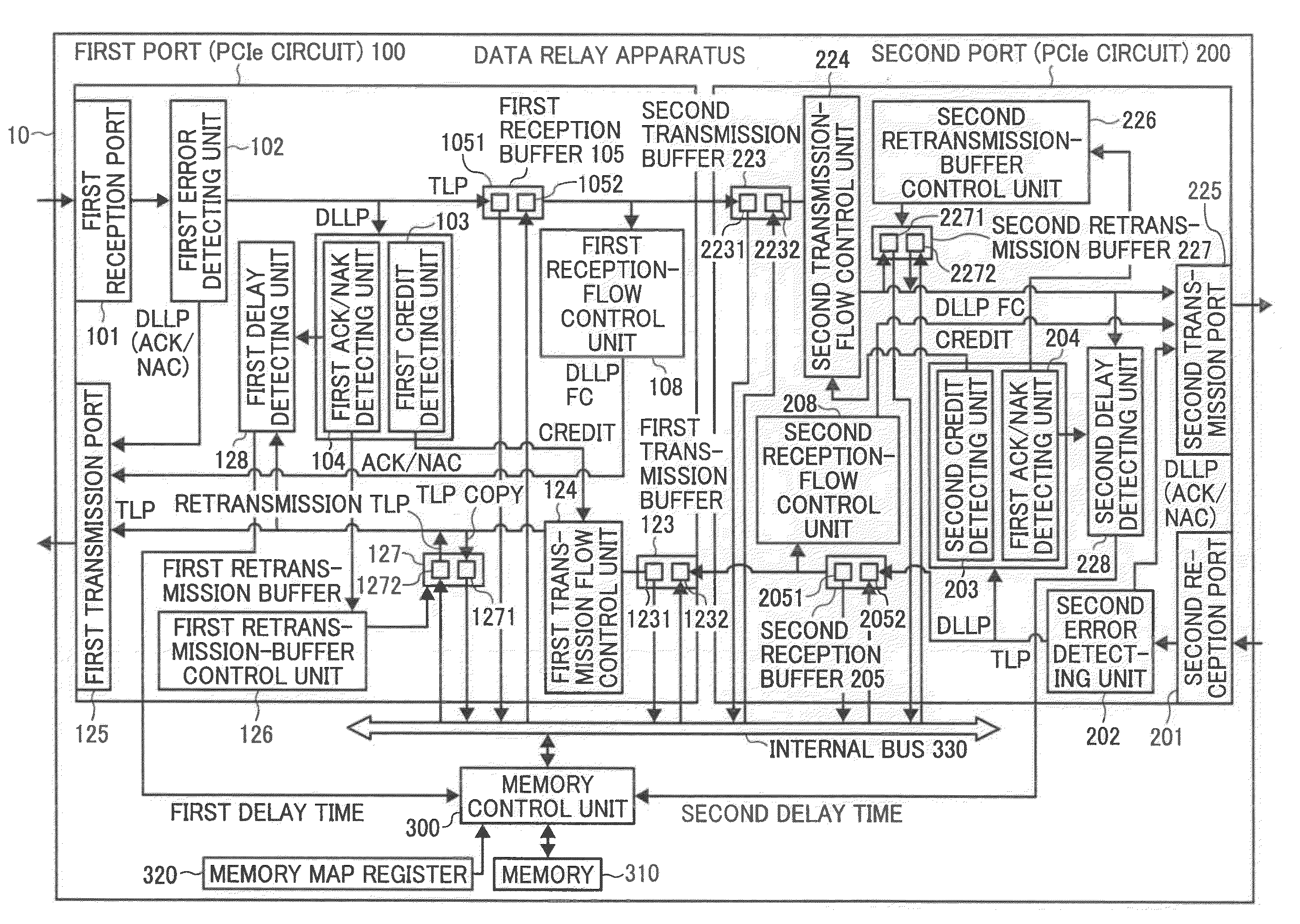
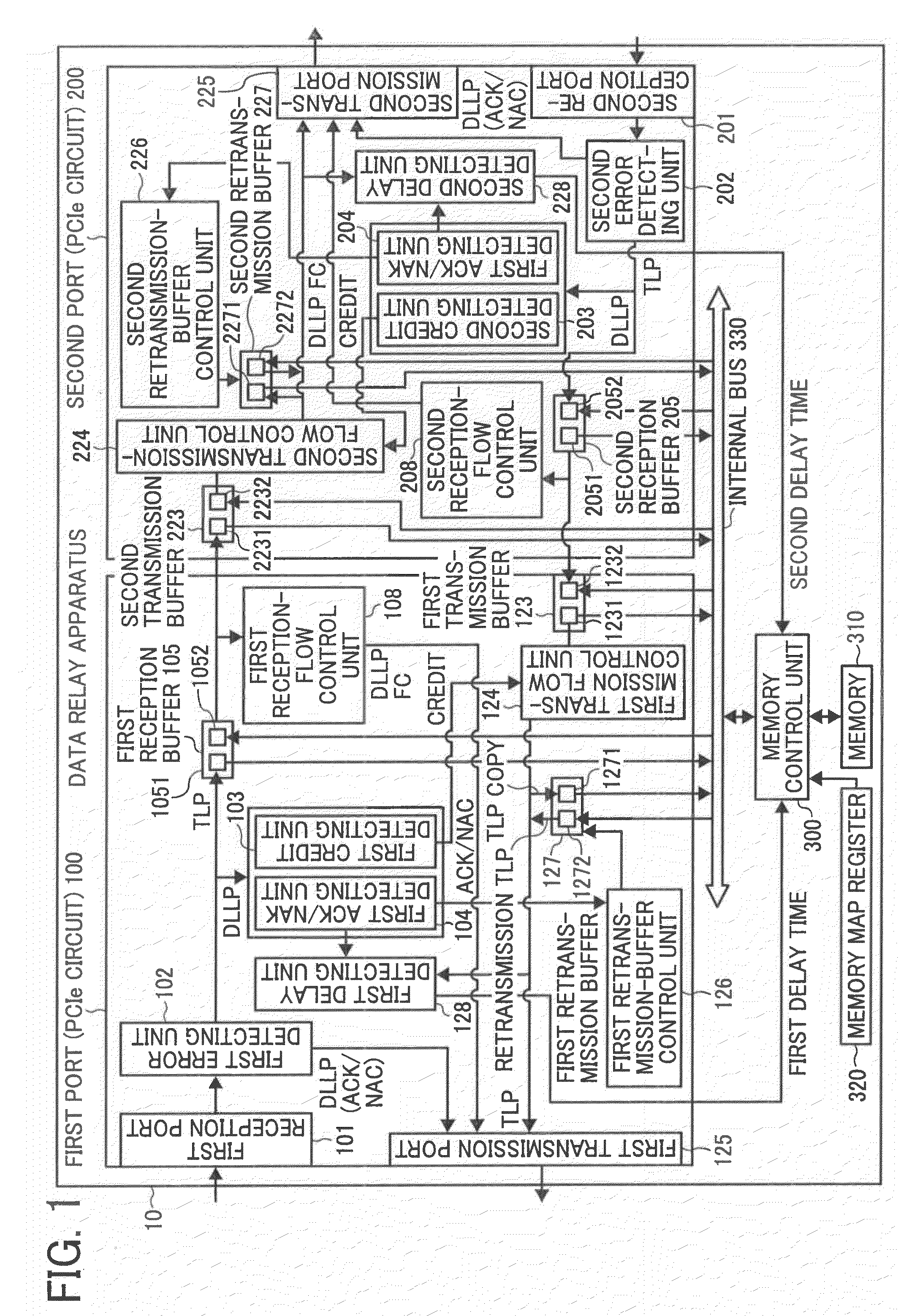
[0067]FIG. 1 is a block diagram of an exemplary configuration of a data relay apparatus 10 according to a first embodiment of the present invention. The data relay apparatus 10 is a data transfer apparatus for transferring packet data. While performing data transfer, for example, the peripheral component interconnect express (PCIe) standard is employed and packet data including transaction layer packets (TLPs) and data link layer packets (DLLPs) such as acknowledgement (ACK) packets, negative acknowledgement (NAK) packets, and flow control (FC) packets is transferred. The TLPs are packets for holding requests or data and the DLLPs are packets transferred for the control purpose.

[0068]The data relay apparatus 10 includes a first port 100, a second port 200, a memory control unit 300, and a memory map register 320. The first port 100, the second port 200, and the memory control unit 300 are interconnected with an internal bus 330. Each of the first port 100 and the second port 200 is ...

second embodiment

[0122]FIG. 16 is a block diagram of an exemplary configuration of a PCIe switch 12 functioning as a data relay device that is a data transfer device according to a second embodiment of the present invention. The PCIe switch 12 includes the first port 100 and the second port 200 as well as includes a third port (PCIe circuit) 400 that has an identical configuration to the configurations of the first port 100 and the second port 200. That is, the third port 400 includes a third reception buffer 401, a third transmission buffer 402, and a third retransmission buffer 403. Each of the buffers 401 to 403 carries out packet data (TLP) transfer with the memory 310 via the internal bus 330. In this way, since the PCIe switch 12 includes a plurality of ports, it is possible to perform mutual communication with a plurality of devices.

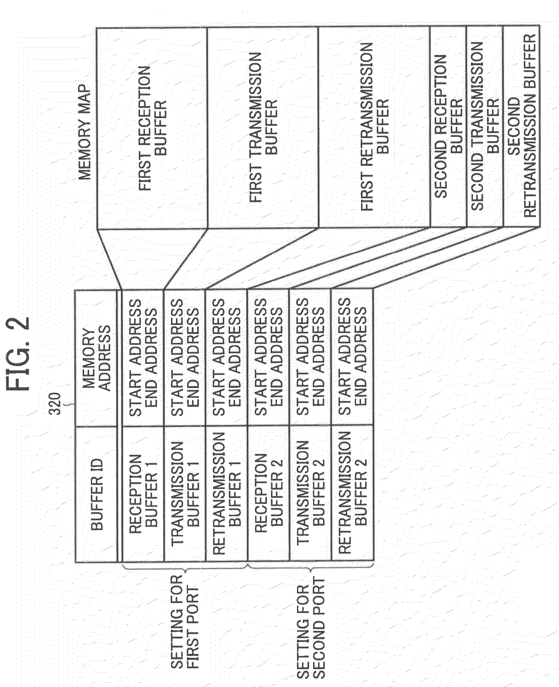
[0123]The memory control unit 300 refers to a memory map having the buffer space allocated to the first port 100, the second port 200, and the third port 400 so a...


PUM


Abstract

A data transfer apparatus includes: a first port and a second port that communicate data; a memory unit that stores the data; and a securing unit that secures, when a first time period starting from transmission of data up to reception of a response to transmitted data at the first port is longer than a second time period starting from transmission of data up to reception of a response to transmitted data at the second port, a first memory space that is used in data transfer in the first port so as for the first memory space to have a larger size than a size of a second memory space used in data transfer in the second port.

Description

CROSS-REFERENCE TO RELATED APPLICATIONS[0001]The present application claims priority to and incorporates by reference the entire contents of Japanese Patent Application No. 2009-212471 filed in Japan on Sep. 14, 2009 and Japanese Patent Application No. 2010-123480 filed in Japan on May 28, 2010.BACKGROUND OF THE INVENTION[0002]1. Field of the Invention[0003]The present invention relates to a data transfer apparatus including communication ports for communicating packet data, relates to a data transfer device, and relates to a data transfer method for a data transfer apparatus.[0004]2. Description of the Related Art[0005]The high-speed serial transmission technology using such as the peripheral component interconnect (PCI) express (hereinafter, referred to as “PCIe”) technology has become popular and is also being implemented for image buses installed in multifunction peripherals or the like. In recent years, along with the popularization of the PCIe technology, there has been a rise...

Claims


Application Information

Patent Timeline
Patent Type & Authority Applications(United States)
IPC IPC(8): G06F12/00
CPCG06F13/00G06F13/4059G06F2213/0026
Inventor IKEDA, JUNICHI
Owner RICOH KK
Learn More